I got this a long time ago from a shop called T J Hughes on Argyle Street in Glasgow.
They had a large display of fibre optic Xmas trees that had a very distinctive appearance compared to the simpler ones with fixed colour changing LEDs. I "explored" one in the shop and when I saw the rotating LED module I immediately bought one.
I'm not sure if there was an issue with reliability, as I've never seen them since.
This video shows the layout of the PCB and slip-ring assembly, which has proper carbon brushes, but sadly not copper or brass slip rings. I also removed all the existing LEDs from the PCB to reveal what they originally intended for the full colour set, and then modified it with my own choice of colours.
No link for this item, as I don't even know if it's still available. But our fave big Chinese warehouse does have a wide range of industrial grade slip rings and brushes for your own projects.
Here's a random (affiliate) link to a range designed for high current things like candy floss / cotton candy machines:-
https://s.click.aliexpress.com/e/_c3AlaaVn
You can use that to launch a wild industrial component adventure on AliX.
If you enjoy my videos, supporting the channel on Patreon helps keep it independent of YouTube's quirks, avoids intrusive mid-video adverts, gives early access, bonus footage and regular quiet Patreon live streams.
https://www.patreon.com/bigclive
Alternatively, for a single coffee contribution you can use PayPal:-
https://www.paypal.com/paypalme/bigclive
#ElectronicsCreators
Оглавление (3 сегментов)
Segment 1 (00:00 - 05:00)
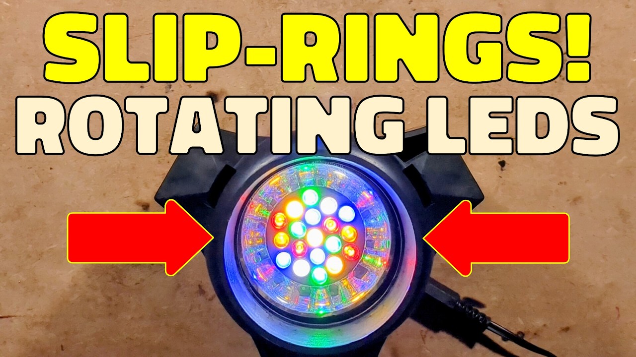
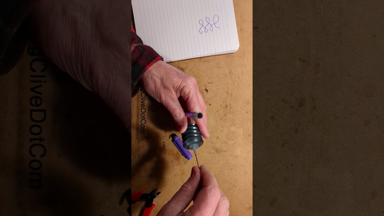
It's the return of the fiber optic flowers and there's a reason for this because the illuminator that's currently illuminating them is very odd. It's LED based but it's not got a color wheel and it's not just feeding the LEDs up and down. It's actually using slip rings and rotating a disc of LEDs underneath the fibers and you can see the green traverses around in a pattern as it rotates round in that disc. Let's take a closer look at that. And before I show the unit, I will give you a flicker alert because it is using AC rectified with very minimal smoothing. Are you ready for this? Here's what's inside. There is a reflector rotating but ultimately it is just seven LEDs but it could be so more as you'll see in a moment. Let me open this up. So the unit is held together with three screws on the base and if we pop those screws out to reveal the mechanism we will see a classic synchronous motor that you'd normally found in the traditional tungsten fiber optic units. I'll just pop this last screw out, brush them off to the side and then dump the inside out. What do we have? We have a resistor that I have clearly added at some point because uh the motor would otherwise get quite hot. Maybe the resistor value could have been a bit lower though. Uh we've got a set of real carbon brushes here with uh the slip rings which aren't brass or copper. That would have been nice to have been brass copper and then we've got this little uh reflector which is looking very sad. It's all the metallization is uh the most of it. And it is pressed in, latched in quite tightly I have to say. Is it going to come out? Am I going to break it? Uh let me try sitting that down level and uh and getting that out. It is just press clipped in. It's just refusing to come out. That's odd. Why is it refusing to come out? Anyway, yeah, that's not helpful. Let me poke it with a pointy thing. I don't think there's anything really holding this in. Not sure why it's not wanting to come out. There it goes. And this is not just uh the reflector for widening the splatter of light, but this actually clamps the circuit board in. Um right. Okay, tell you what, I shall take some pictures of the circuit board and we can explore it. Okay, let's explore. The AC comes on in these two connections here and immediately goes through a discrete bridge rectifier. And then there's a smoothing capacitor over here, 47 microfarad, 25 V. And it feeds multiple circuits of LEDs with their own resistors. And it's notable that this is designed to take a lot more LEDs, but they've been bridging sections of the LEDs out uh well, LED positions out to allow current flow through the rest of the circuit. It's also interesting to note that there's a cluster of blue positioned here, cluster of green. I wonder why they did it in such big color clusters and then blue, red, green and blue, red, green. Odd. But if we take a look at the back of the circuit board, we can see that the LEDs are not arranged. That is quite annoying. I'll unplug it. It's also grilling the LEDs. Surprise, about 30 mA. Um but we can see that the LEDs are wired in odd multiples. Now, these ones were bridged out, meaning that they were just pairs of LEDs effectively. Except this one, which was just a single LED in its own. Uh its resistor was the fi- highest value, 510 ohm. But uh they're wired in strange configurations. You've got three here, you've got four here, two here, uh three, then four, and then three. You'd have thought they'd have made uh instead of having two, they'd actually have just basically added one in from this set and actually had groups of three. Unless it's just the fact that they are allowing to bridge them out like this when they only want to use the central cluster. But, anyway, I have the urge Well, actually, I'll show you the circuit diagram first. You will probably already know more or less what it is. I shall zoom in this. Zoom. It's not that complicated. AC in, 12-V AC, supposedly floating quite high. Uh the synchronous motor, which should be a decent load in that. Then the slip rings. Didn't really know. I've never done slip rings on electronic circuit diagram before. I just put contacts rubbing onto blocks. I have to check that up. A bridge rectifier, the smoothing capacitor, the that produces the 14. 8-V 8. 5-V rail. And then we've got the unusual configurations of three, four, two, three, four. And then it swaps the
Segment 2 (05:00 - 10:00)
resistor position to the positive rail. And then we get this one down here. Very strange, this group of LEDs. Right, tell you what, I have an urge then to remove these LEDs and see what colors are actually marked underneath. So, if I zoom down a bit, and I shall uh also focus up a bit, like that. Now, I should what? I'll take these uh lids off first. And technically speaking, I think this is young enough to be in the lead-free era. So, tell you what, I will flow a little bit of fresh solder onto these pads here. Just to make them moist. At this point, maybe the LED would drop out itself, but it rarely does. So, what I'm going to do, I'm going to get this Oh, I can already smell classic synthetic resin bonded paper circuit board material. I'm going to push a bit of silicon sleeving always from aquarium use over that, and then hold it with the fingers like this, pulling down gently, and then heat those pads, and out pops the LED. It's the easiest way to remove it. I'm going to do that to all of them. I'll be back in 1 minute. The LEDs have now been removed, and it reveals that the full spectrum of color that they originally designed it to take is quite distinct clusters of green and blue and green with just a smattering of red, and then two whites. Notably, in the case of the two whites, it's the two LEDs that were on their own. That's unusual. But, I have more colors of LEDs. Not a huge number, because most of my LEDs appear to be diffused. Let's move this to the side or side emitting or straw hat. But, here's what I'm thinking of doing, and I'm not sure it's a great idea, because I'm basically repeating a color pattern around. It means that at any time, it's going to look that Say, for instance, as it passes under this cluster of fiber optics, it's basically going to go red, yellow, uh it's blue, yellow, red, warm white, green, cold white, and then it's going to start the blue, yellow, red. So, it's going to sort of half the resolution of the color wheel, as opposed to maybe putting blocks of color. But, I'm adding warm whites in uh cold whites, which it had before, and I'm adding yellows. I wonder if I should have made that one a yellow, as well. No, I'm going to make it warm white, cuz it's brighter than the yellow. The yellow's going to be a sort of low-key player. But, this is the color I'm going to put into it. So, I shall start soldering them in now, and we'll see what it looks like. Okay, that's them in with their newly chosen resistors, very bright and dazzling. Yes. Overall color roughly white on the camera. 50 volts is about 100 milliamps, which is 20 milliamps per circuit, which is kind of what I was aiming for. Quite spicy, but nowhere near as spicy as what the original circuit had. It was really driving LEDs hard. It was going all out. Maybe that's why I never saw these again. So, now I want to zoom out here. Make sure we're in focus. And I want to zoom in a bit. Tack these leads now. These are the ones off the slip rings. I want to tack them onto the circuit board here. So, I shall put this one onto here, which is the AC on. And this one onto there, which is the other AC on. I shall put it on sideways just to save a bit of space here. Lovely. Okay, so when I put this back down, I should be able to sandwich this with the Is there a indenting system? There's not really. I think it really is just wherever it lands, really. So, I shall pop this through here and clip it back into place. Noting that when I added new capacitor, I did leave a little bit of extra space for that. Um and then I shall [clears throat] plug its supply in and uh see if it starts rotating. It may not start rotating because the motor's a bit sluggish. The LEDs are not lit. That's a really bad start, isn't it? Why are the LEDs not like that's because it's uh at some point the slip rings have slid up. Okay, so I have to carefully push that uh carbon brush in. I've pushed both carbon brushes in. That's no joy. — [sighs and gasps] — Right, okay. This is just not going to be a fun thing, is it?
Segment 3 (10:00 - 12:00)
Let me get the spudger. The spudger is better suited to this spudgery type thing, but I shall spudge that carbon brush back. Try not to snap the Oh, it's not going in. It is not going in, is it? At what point do I pause? I'll push that down a little bit. That's the first carbon brush into position. Second carbon brush, I should be able to push from about here. There we go. That should work a lot better now I've done that. Okay, will it work a lot better? Yes, it is working a lot better. Still a bit of shimmer there, but uh right, I'm going to put this back into its case and then we'll try it with the fiber plant. And now the last screw is going in and that should be it more or less complete. This unit is designed to have a base because it was originally designed for fiber optic Christmas trees. Right, zoom out because it's way zoomed in now. Okay, let me get the fiber flowers up. Complete with suspiciously 3D printed looking adapter. Shove that down there. Find the power inlet here. Oh, god, that's a bit cluttered, isn't it? Plug it in and then adjust the lighting to see how this looks. So, I'll do that right now. And this is it with the new color wheel. Is it too cluttered? Should have done it in big chunks of color. And this actually looks okay. There's a slight flicker because the slip rings on this not the slip the it's the slip rings are crap. The brushes are fine cuz they're carbon, but the slip rings aren't the ideal material for this. But that looks all right, but it does look very pastel. I should make sure that's pushed right home. Because the closer it gets to the LEDs, the better. Um you'll get more vivid colors, but that does look okay. Let me know what you think anyway in the description if you think I made the correct color choices there. But now uh that is it. So, let's go back to the bench. So, it's I would say that was a success. It was quite time-consuming to do. Odd that they skimp in the first place. I'd guess maybe they add more LEDs to the larger clusters, the bigger trees. It was just a universal design. But that's it. The current has been moderated down to sensible levels to the LEDs and um it's not very bright in well, the bench the studio lighting, but in the dark it looks very nice. So, I'd say that was a success.