Reflex Training Machine Build - Using Relays, Transistors & Arduino
16:49

Reflex Training Machine Build - Using Relays, Transistors & Arduino

element14 presents 21.05.2026 1 040 просмотров 67 лайков

Machine-readable: Markdown · JSON API · Site index

Поделиться Telegram VK Бот
Транскрипт Скачать .md
Анализ с AI
Описание видео
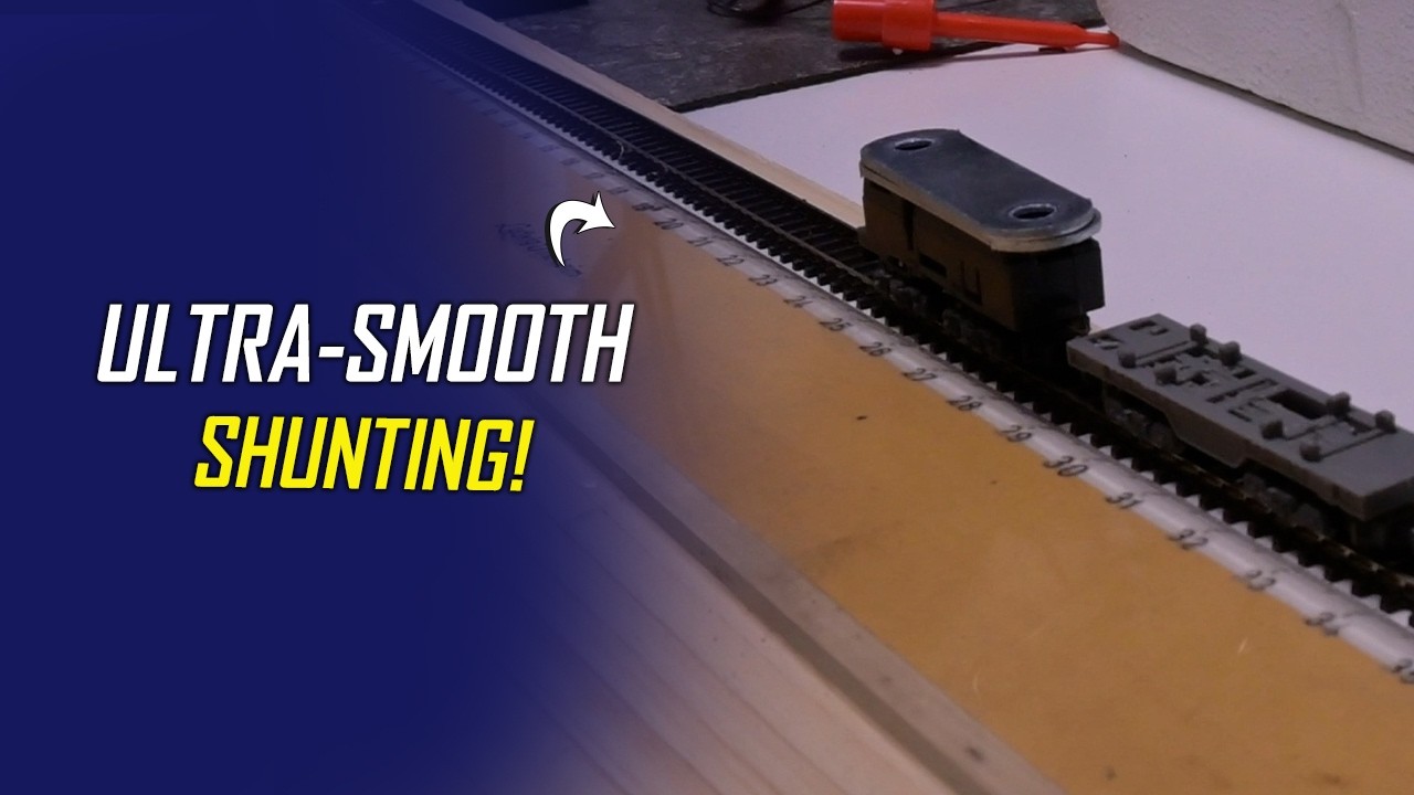
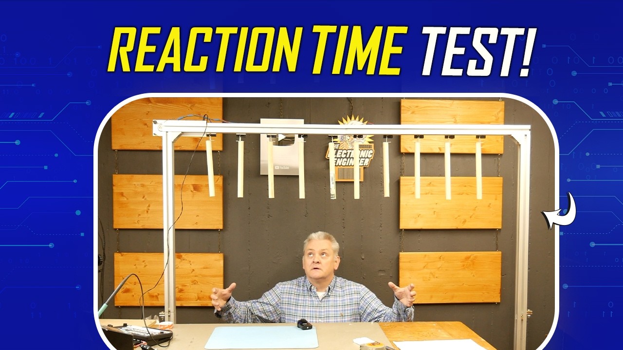
In this video, Mark builds a reaction-based catch game inspired by a classic TV challenge, using an Arduino Nano, relay-driven actuators, and a simple but effective control system. The setup drops sticks at random intervals, testing reflexes while showcasing practical electronics design, from power regulation and PCB assembly to embedded programming and mechanical integration. This project balances accessibility with clever implementation, making it ideal for makers looking to build something interactive and fun, you can find the supporting code on the element14 community: https://bit.ly/4dBqWRE #ArduinoProjects #DIYElectronics #stemprojects [02:20]-Components 
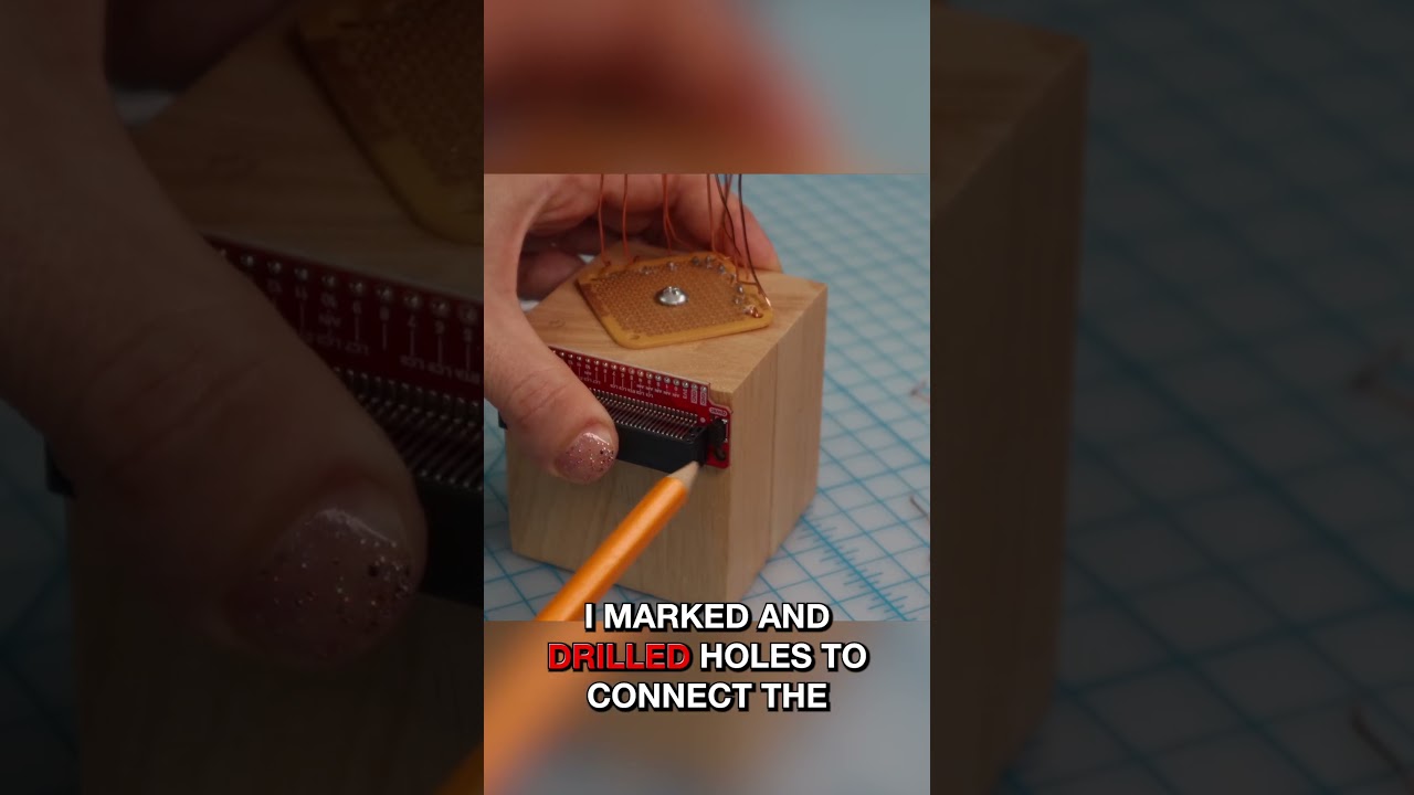
[03:43]-Populating The Board [08:24]-The Base [10:26]-Mark gets Framed [15:09]-The Demo ================================================================================= Engage with the element14 presents team on the element14 Community - suggest builds, find project files and behind the scenes video: https://bit.ly/3tmdewv Visit the element14 Community for more great activities and free hardware: Tech spotlights: https://bit.ly/3qPrDhM RoadTest and Reviews: https://bit.ly/3pV5Bux Project14: https://bit.ly/31wbnJY

Оглавление (6 сегментов)

<Untitled Chapter 1>

Hi. Welcome back to Army 14 Presents. My name is Mark. Today, I'll be showing you how you can build your own game setup. And I'm not talking about a computer, but I'm talking about an actual game. We're going to build a rig. Um some sort of rig, I don't know yet. We'll see later. Um and it will hold several staffs that will drop down randomly one by one. And while standing underneath it, you need to try to catch them. That's the game. So, let's get started. Okay, so let me walk you through the schematics. Okay, so the schematic is not complicated. I know I always say it, but it's true. Um we have a power section. And I will feed that using a 12-V power supply, an adapter. Um or if you're outdoors, you could even use a battery. Uh a switch to turn it on and off. And a standard regulator to create 8 V that I need for the relay to give it a powerful kick. I'll get to that in a minute. I know it's not the most elegant regulator uh nowadays, but it's analog and it's proven and tested to work, so that's why I use it. Uh we have our Arduino Nano. And the Arduino Nano has a push button that I can use to start a new game. Or I can even give it a double function, for example, to put the system in an advanced mode for uh a more difficult game. And then we also have a LED to indicate if an advanced mode has been activated. Um we have a sound section. And basically, that's a P PMW. Um or PWM, I must say. Pulse width modulation, sorry. That's used to drive a speaker. And it's only used to generate a beeping sound to indicate the start and the end of the game. And it'll do the job quick and dirty. Then we have our relay drivers and same here, a transistor that will switch a relay. The relay is actually the one holding the sticks to drop and I use a door latch relay for that and I did it 10 times. I only drew two in the schematics, but of course we're going to create 10 because we have 10 sticks.

Components

Okay, so let me show you the components. Okay, so we have our Arduino Nano. We have two sockets to install the a push button and a power switch. We have some resistors that you see here. Our transistors. The power regulator. A speaker. The light indicator. Some diodes. Uh universal diodes will do. This is to protect the transistors from the spikes that are generated by the coils that you see here. Uh we have some capacitors. A connector. And yeah, well these are actually the locking mechanism that I will show you separately. This is what we're looking at. Goes in here. And then when it's powered on, this will happen. Yeah. Simple as that. I turn on the power and then it's hanging like this and the stick that's attached to the to this handle will simply drop. And of course we're going to put all of that on a nice universal PCB. So it's time to start heating up the soldering iron and you know, let's get

Populating The Board

to it. Okay, so first things first, I'm going to put the headers on the microcontroller and then I'm going to insert it there. Uh I already made a power section, which basically is a regulator, uh the switch, and a few capacitors. And that's enough for the power. Um I also placed a connector with a resistor, which is for the LED. Um Honestly, it's already on the board because I forgot to turn on the or I forgot to press the record button when I started. So, sorry for that. For now, let's continue. The push button is connected to D2, and the neighbor of D2 is ground, so that way I can just pin the connector down and, you know, um use the traces that are already on the plate. Okay, so Arduino, speaker, and power supply are done. What's left are the drivers. And let me start by doing the resistors on the ports cuz that's the easy part. And we start at pin whatever, 12, D12. D12. I know this is not the most elegant way of soldering, but I have to make do with what I have at home. Um Yes, the soldering might look a bit chaotic, but I promise you that will all be fixed under the microscope later. Now, I'm just going to remove some of the wires so it's easier to solder the rest under the microscope. — Okay, so I'm going to put the transistors. And we have 10 of those. — Like that. And after that, I can align everything. Okay. So, those are almost all the components. Still need to add the diodes. Almost forgot about that. That would be a pity. Okay, so all components are on the board. Um which means I will be moving it to the microscope to finish up the soldering. — Yeah, at this point, I'm using a Dremel tool to remove some copper that I don't need. And if I don't, we will have a big short circuit. So, this needs to be done. You can just follow the schematics. And of course, it depends on your layout. Um where you put your components, and then you have to see which traces needs removing. Okay, so for this project, I have to use some wires because I didn't design a PCB, and you know, the traces are not there. So, I have to make the connections manually by using wire. I have some fine wires, and um all what I'm doing here is connecting the dots and you know, you just follow the schematic again like with the traces before. Um, follow the schematics and you'll be fine. — I first encountered this game in a TV show long ago like 20 years ago. It's something called the Honeymoon Quiz, very popular show on TV. And this is where I first saw a setup like this and I always figured at some point I will have to build one. I'm going to have a lot of fun with this especially with the kids at my unit school. They can play with it whenever we have an event and um I'm sure we'll all have some fun. —

The Base

— Okay, so I made a base plate with my 3D printer that I can use to mount the PCB on the speaker, the LED and the switch to keep wires short and compact and then all I need to wire up. The longer wires are the activators. I will do that in a bit. We'll start with the PCB first. Okay, so this is the base plate. Uh, I have two old spacers that I used in a spectrum analyzer and I don't use them anymore so those are nice uh to be used as a spacer. We'll put them here and here. And then I'll all I need to do is screw on the PCB. So let's start with that. Not yet. That was to be expected. Like so. Now, I expected to fit. Perfect. Like so. Okay, so let me attach the wires to the speaker, the switch, and the LED, — and then we'll move on to the aluminum frame. Okay, so let's start with the wires for the switch. — So there we have it. That's the PCB with the wiring. Like so. — So here we have it, the assembled PCB with the basic wiring, the speaker, the switch, and the LED. And of course, all we need to connect is a the actuators, and we do that to that connector. It has one common power, and the rest each pin will be connected to a

Mark gets Framed

actuator. Okay, so now we are going to assemble um the actuators on the frame. And you can build your own frame, you can use some wood uh uh bars or whatever you have laying around that can make a frame. It's not that spectacular. Um but I happen to have uh aluminum frames laying around from an old table that I had for my laser cutter. And it's called item frame. Um we have we're going to have two stands and a top bar on top, of course, um which is going to be this one. And this will hold all the stuff that will drop down. So for the time being, let me put aside the stands, and let's focus on this one. Okay, so this is where the electronics is going to rest. And we might as well do that, slide in two of these nuts, specially made for this frame. Of course, um it's a test setup. When I'm going to use this uh on a fair or uh some children's party, of course, I will put a casing over the electronics. Um and make it all nice and tidy. But, for now, it's an experimental setup. Let's call it that, a prototype, if you will. Uh for that, this will be good enough. Now, we're going to mount the actuators. And I do have to mount them somewhere like this. And then several on the whole rail. And then later, sticks will be attached here. And it can drop. Okay, to attach these uh actuators, I'm going to use uh double-sided tape. Make sure you use proper double-sided tape that can hold a lot of force. Um because you don't want the uh actuator to fall off completely. You only want the stick to drop when it's uh when the program says so to do so. Um so, I bought some new tape that has some uh nice uh force. It says about 70 kg per square meter. Uh we don't have a square meter, but we still have a lot of force left. Because what we are going to use to drop are these little wooden sticks. And they're not that heavy. Now, before you attach the tape, make sure you clean the surface with some sort of alcohol uh to remove any grease that's left, because it will help you with the tape. Do the whole railing. Yeah, like so. And now, I will have to clean all these little Well, they're not really little, are they? — The good thing is all I need to worry about later is which wire is the common and all the other wires I can just connect randomly because the activators are controlled randomly. Okay, so let's connect the activators or the wiring of the activators to the actual PCB. Well, the most easy wire or actually the one wire that has a dedicated pin is the power. Yep. And then I'm just going to do the last one. So, the electronics is all done. We still need to do some mechanical work which is attaching the clips to the stick for it to properly work later. So, now with all the six ready, it's time for some testing.

The Demo

— As you might have guessed, the space in this room is kind of limited. The ceiling is up here, so I cannot elevate it too much. So, for the test, I'm just going to kneel down. That's a failure. Crap. You are going TO BE MINE. — AS YOU CAN GUESS, THIS IS MORE DIFFICULT THAN I THAN — I EXPECTED. GREAT. See you next time. I'm going to have a lot of fun with this. So, this is all I have for you today. I hope you enjoyed it. Remember, we have a project page at the Element 14 community. All the information you need to rebuild this project is there. And of course, you can leave comments or make suggestions about project. And as always, I'll do my best to answer each and every one of you. Until then, I see you next time. —

Другие видео автора — element14 presents

Ctrl+V

Экстракт Знаний в Telegram

Экстракты и дистилляты из лучших YouTube-каналов — сразу после публикации.

Подписаться

Дайджест Экстрактов

Лучшие методички за неделю — каждый понедельник