Computer noises

Computer noises

Ben Eater 213 638 просмотров 12 954 лайков

Machine-readable: Markdown · JSON API · Site index

Поделиться Telegram VK Бот
Транскрипт Скачать .md
Анализ с AI
Описание видео
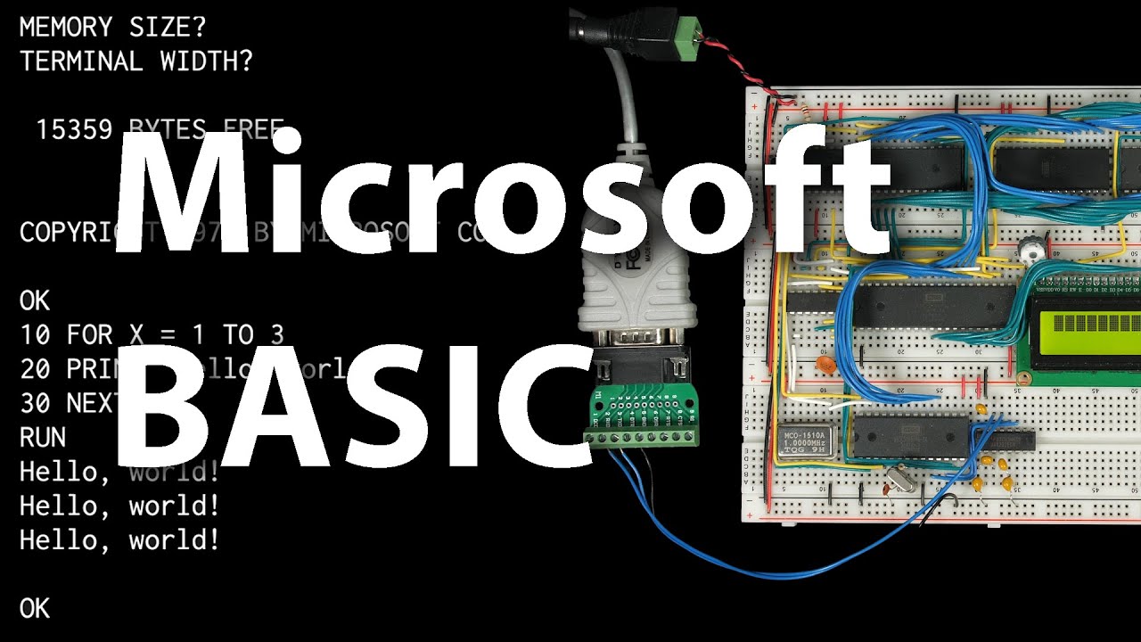
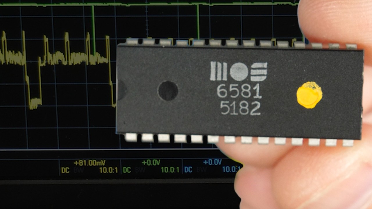
I show the simplest way to get a computer to make noise—amplifying a square wave. I add a BEEP instruction to MSBASIC that lets you generate a beep at a particular frequency and use it to make some very rudimentary music. Support these videos on Patreon: https://www.patreon.com/beneater or https://eater.net/support for other ways to support. ------------------ Social media: Website: https://www.eater.net Twitter: https://x.com/beneater Patreon: https://patreon.com/beneater Reddit: https://www.reddit.com/r/beneater Special thanks to these supporters for making this video possible: Adrien Friggeri, Aleksey Smolenchuk, aliceitc, Anthony Weems, anula, Axel Hanikel, Ben, Ben Cochran, Ben Kamens, Benjamin D. Williams, Benjamin Elder, Benjamin Keil, Benji Bromberg, Bill Cooksey, Binh Tran, Bradley Stach, Brian Haug, Carl Fooks, Carsten Schwender, Chad Fertig, Chai, Chris Anders, Chris Lajoie, Craig Hawco, criis, Cristi Cobzarenco, Daniel Tang, Dave Westwood, David Clark, David Cox, David Dawkins, David House, David Sastre Medina, David Turner, Dean Winger, Deep Kalra, DemoniacDeath, Dennis Henderson, Derek Chandler, Dilip Gowda, Dirk Sperling, Dmitry Guyvoronsky, Dustin Schoenbrun, Dzevad Trumic, Emilio Mendoza, Eric Dynowski, Erik Chancy, Ethan Sifferman, Eugene Bulkin, Evan Serrano, Evan Thayer, Eveli László, garmata, George Harris, George Miroshnykov, Glen Jarvis, Glenn Davidson, Gregory Burns, GusGold, Henry Lerner, Hovis Biddle, Ingo Eble, Ingram Leedy, Isaac Parker, Jack McKinney, James Capuder, James Chacon, Jason DeStefano, Jason Grim, Jason Thorpe, JavaXP, Jaxon Ketterman, Jefferson Hunt, jemmons, Jesse Miller, Jim Kelly, Jim Knowler, Jim Rees, Joe Beda, Joel, John Haugabook, John Rivoire, Jon Dugan, Jonn Miller, Josh Smith, Justin Berry, Justin Williams, Kai Wells, Kefen, Kennard Smith, Kenneth Christensen, Kristian Høy Horsberg, Kyle Kellogg, Lambda GPU Workstations, Larry Scherr, László Bácsi, Lithou, Marcel Wysocki, Mark Day, Mark Frankford, melvin2001, MICHAEL SLASS, Michael Tedder, Michael Timbrook, mikebad, Miles Macchiaroli, Mlok Karel, Nate Welch, Nicholas Counts, Nicholas Moresco, Nick Chapman, NormalLuser, Olivier HUBER, Örn Arnarson, Owen Arnett, Pat Nakajima, Paul Heller, Paul Pluzhnikov, Pete Dietl, Philip Hofstetter, Ponytail Bob, ProgrammerDor, Randal Masutani, Randy True, raoulvp, real_huitz, Richard Wagoner, Robert Diaz, Robert Walsh, Robey Pointer, Roland Munsil, Ryan, Ryan Morrison, Sachin Chitale, Sagnik Bhattacharya, Sam Sturgis, Scott Holmes, Sean Patrick O’Brien, Sebastian Kopeć, SergeantBiggs, Sergey Kruk, Sergey Ten, SonOfSofaman, sorek.uk, spookybassoon, Stanley Benoit, Stefan Nesinger, Stéphane Dumont, Stephen Kovalcik, Stephen Riley, Steve Jones, Steve Harris, This person's name is too hard to pronounce, Thomas Eriksen, Tim Oriol, Tim Sanders, Tim Walkowski, Tom, Tom Smith, tremors08, Trevor Johnston, Trey Webb, tryonlinux, Tyler Latham, Vaida Narušė, Victor Kazakov, Warren Miller, Wraithan McCarroll

Оглавление (4 сегментов)

Segment 1 (00:00 - 05:00)

There are all sorts of ways to get a computer to synthesize sounds, but by far the simplest is just by generating square waves, and it's a digital computer, so square waves are kind of what it already does. Just toggling a bit on and off will produce a square wave. So, if we can just find a way to toggle a bit on and off at a particular frequency and hook that up to an amplifier and a speaker, then by adjusting that frequency, we can change the tone that it produces. And just a quick reminder that I sell these kits to build your own 6502 computer, including the serial interface and programmer that I use. All of that's available on my website, eater. net/6502. So, how do we toggle a bit on and off at a particular frequency? Well, we've already got this 6522 versatile interface adapter chip that we're using to interface with the LCD and a couple other things here. And it actually has a timer feature that will do exactly what we want. So, if we look at the data sheet for the 6522 versatile interface adapter, there's a section here that talks about timer one operation. And if we just read what it says, it says timer 1 consists of two 8-bit latches and a 16- bit counter. Uh the latches store data which is loaded into the counter. And once the counter is loaded under program control, it decrements at phase 2 clock rate. So, what that's saying is we've got this 16- bit counter that starts at a particular value that we can set and then it counts down at the clock rate of the computer. And in our case, our computer's clock is running at 1 MHz. So that means it's going to countd down uh at a million times per second. And there's also a separate, it says two 8bit latches, but essentially it's a 16- bit latch that stores the start value of the counter. Then it says upon reaching zero, um, and it talks about a bunch of stuff that it does with interrupts that we don't particularly care about. But then it goes on to say it says or will automatically transfer the contents of the latches, that's that start value, into the counter and proceed to decrement again. So it's saying when the timer gets to zero, it can automatically reset it and restart the timer again with the same value. So then it goes on to say the counter may also be programmed to invert the output signal on PB7 each time it reaches a count of zero. And that's exactly what we're looking for. It can invert this uh signal on PB7 at a regular interval. And inverting a signal at a regular interval is going to give us a square wave. So if we look at the pin out for the 6522 chip, which I'll see if I can find here. Here we go. PB7 is this pin right here. It's pin 17. And so pin 17 is that pin uh right here, which thankfully we're not using. We're using uh PB0 through PB6 for the LCD. Uh but thankfully PB7 is not currently in use. So we should be able to generate a square wave on that pin there. Um and then hopefully find a way to use that to make some sound. So programmatically, how do we do that? Well, we've got these uh bits six and seven of the auxiliary control register uh allow selection of the timer one operating modes. So, if we look at the auxiliary control register here, we've got these two bits here uh bit six and seven for T1 timer control. So, at two bits, that gives us four different options. Uh basically, do we want the timer to run continuously and do we want PB7 enabled? So, with both bits zero, the timer runs once and PB7 is disabled. But we want this mode here where the timer runs continuously and PB7 is enabled which gives us a square wave output on pin PB7. Then to set the frequency of that square wave, we need to set how long the timer runs. And so there's registers for the counter itself, which are registers four and five. And then there's also registers for the latch values, which is registers six and seven. And so these latches hold a 16- bit value that the counter is going to reset to once it reaches zero. But if we look at the counter registers and how those work, there are two 8- bit registers, a low and high, which gives us a 16- bit counter. And if we write to the low register, it says it's going to load eight bits into the timer one low order latches. And then the latch contents are transferred into the low counter. So by writing to the counter, we're actually writing to the latches. And then that value is being transferred to the counter at the time that the high order counter is loaded. So we load this first and then when we write to the high order counter uh we write eight bits into the high order latches and then also both the high and low order latches are transferred into the counter and that initiates the countdown. So the way this works is really no need to mess around with these latch registers at all. We'll just put a 16- bit value into the counter registers or I guess more specifically we'll write a 16- bit value into registers four and five. that'll automatically then copy that value or that'll put that value into the latch registers as well as starting the timer. So if we write a 16- bit value to registers four and five and then we set bits six and seven in the auxiliary control register that should generate square waves. So let's give that a try. I'm going to continue what I've done in previous videos and add a new instruction to basic for our square wave generation. I'll add a new keyword beep since that's pretty descriptive of the result we'll get and I'll include a new file sound. s

Segment 2 (05:00 - 10:00)

which is where we'll add our code. Then I'll create that new file and this is going to be in the code segment. And I'll wrap everything in here with uh an ifde defe so that it's only included when building basic for my computer. And if any of this is unclear, I've got several videos on adding new instructions to Microsoft Basic that go into way more detail on what I'm doing right here. But with this new instruction, I'll start by defining constants for the registers that we were just looking at. We've got timer 1 counter low, and that's at address 6004. And then timer 1 counter high is at address 6005. And remember, the data sheet says that these are registers four and five. And the way I've designed the computer, the uh versatile interface adapter chip registers start at address 600 0. And so that's how you get to addresses 64 and 6005. Then the auxiliary control register is register B. So that's going to be at address 600B. Then for the beep instruction, we'll have it take a parameter, which is the timer counter value. And again, you can check out my previous video on parsing parameters in a custom instruction for Microsoft Basic. Um, but to do that we'll call formula eval and then make int to parse a 16- bit integer parameter. And as I showed in my previous video, this will put that parameter into the uh floatingoint accumulator uh values. So fac and f3. So we can take f+4 and copy it to the low bite of the counter and take f plus 3 and copy it to the high bite of the counter. So that way if we call this beep instruction, we say let's say we just say beep 1 2 3 4. Well, this formula val will evaluate that 1 2 3 4 and make int will make an integer from it, which we can then find as a 16- bit value in FAC++4 and FAC plus 3. And so what this is doing is it's just taking whatever that 16 bit uh parameter is and storing it in the timer one uh 16 bit registers, you know, between the low and the high bite. And as soon as we do that, that'll start the timer. Then if we load uh C 0 which is just the first two bits set and store that in the auxiliary control register that'll set up the timer like we saw to output a square wave on that PB7 pin. And then once we've done that we can just return from the sub routine. And so that should be enough to take a parameter and generate a square wave. But before we try this out I'll add one other feature which is a way to turn off the square wave. So when we get this parameter here I'll check to see if it's zero because a square wave with a period of zero you know doesn't make sense anyway. So we could say if the parameter was zero, we'll use that as a key to stop the square wave output. So to check if it's zero, we'll load FAC plus4 and then or it with FAC plus3. And the only way that the result of oring these two bytes um you know FAC plus4 and FAC plus 3. The only uh way that the result of oring those together is zero is if both bytes were zero to start with because if either of them was non zero then the result of oring them together would also be non zero. So if they're both zero, then we could do a branch if equal, which will branch if the result of the ore is zero to um call label silent. Then I'll add that label down here at the bottom and stop the square wave output by loading a zero and then storing that into the control register uh before just returning from the sub routine. So let's try this out and see what it does. I'll save that, build it, and then write the resulting image to an EPROM. So, I'll put the EPROM back in the computer, reset, and then run basic at address 800 0. So, now if I do beep 100, that should generate a square wave of some sort. So, let's hook an oscilloscope up to pin PB7 here and see what we get. So, there we go. That looks like a square wave. And so now each division here is 100 microsconds which makes sense because the 100 here is the number of clock cycles uh before it alternates and the computer clock is running at 1 MHz. So it should alternate every 100 micro. So if we say beep 200 then it doubles the period. And if we want a particular frequency we just have to calculate the period. So for example A440 which is the musical note a above middle C is 440 hertz. So, if we take a 1 MHz clock and divide that by 440 Hz, we get about 2273. So, let's try beep 2273. There we go. And that's actually closer to 220 htz here. And that makes sense because this frequency is from rising edge to rising edge, not how often it alternates. So, if we actually want a frequency of 440 htz, we want to divide that by two. We want about half of that. So, let's try beep 1136. There we go. And that's closer to 440 Hz. So, we've got a square wave. Now, how do we hook up a speaker so we can hear it? Well, I have this. It's just a generic little speaker, you know, 8 ohm, 2 watt. But I can't just directly connect this to the PB7 output pin.

Segment 3 (10:00 - 15:00)

Since the 6522 here can only uh output a few mills of power, it can't drive a speaker. But we can use an amplifier like this little LM 386 audio amplifier chip to amplify the square wave output and drive the speaker. So here's the data sheet for the LM 386 low voltage audio power amplifier. And I'm just going to jump to this section here with uh a typical application uh because it says here this shows the minimum part count application that can be implemented using the LM386. And that sounds like exactly what we want. So I'm just going to go ahead and build this. Get the oscilloscope out of here for now. So there's the LM 386. I'll start by hooking up power and ground. And so power goes to pin six. Ground goes to pin 4. Then we have the inverting input pin two here. That also goes to ground. Then the input is pin three. And it's hooked up to a 10k potentiometer. So we'll go from pin three over to here. And then we have a 10k potentiometer, one side of which goes to ground. Here's the potentiometer. And then the other side of the potentiometer is the input. So we'll run that over to pin PB7 here. So that's our input. Then the output pin five has this 05 microfarad capacitor going through a 10 ohm resistor to ground. So we'll go to pin five. We've got a 0. 05 microfarad capacitor that goes to a 10 ohm resistor which I'll take to ground here hiding underneath the LCD. And then all of that's in parallel with a 250 microfarad capacitor going to the speaker. So we've got our 250 microfarad capacitor that goes to the speaker. And then the other side of the speaker goes to ground. And there we go. That's making some noise. Let me That's our volume. That's a little bit better. And then I should be able to do beep zero to get that to shut up. There we go. Let's try some other numbers. We'll do beep 200, beep 500, beep 10,000. And so that seems to work. Now the other thing I could do is add a parameter to the beep command that says how long to beep for. So it'll you know delay for a certain period of time and then automatically stop beeping. So here after we start the square wave let's get another parameter. We can jump subine checkcom to tell basic that we're expecting a comma. Then jump subine get bite to get another parameter as a number from 0 to 255 which uh it'll put into the x register. And then we'll use this bite as an indication of how long to delay. So now I can just write a delay loop. So I'll start with a label delay and then I'll decrement the x register and then branch if not equal back to delay. And so that'll just sit in this loop decrementing x each time until x gets to zero. Um and then it'll fall through and return from the sub routine. And so how long that it takes in this loop depends on what x is which is this parameter that we're getting here this bite which could be 0 to 255. But even you know looping through 255 times won't really take that long. So I you know I'd like to waste some more time in the loop. So I could add a couple noops here you know but even that is probably not going to delay enough. So what I'll do is actually create another loop inside this loop. So this loop will be delay one. And then I'll create another loop inside here called delay two. And before the second loop, I'll load the Y register with FF so that we'll go through the inner loop 255 times for every time that we go through the outer loop. And then guess I can leave the no ops in here. And then decrement Y and branch not equal back to delay 2. So now we'll go through this inner delay 2 loop here 255 times for every one time we go through the outer delay one loop. And that outer delay one loop will go through however many times was passed in by this second uh parameter here. So that should allow us to pass this second parameter to control how long um we're actually beeping for. Then when we get to the bottom of the delay loop instead of returning from sub routine we'll just fall through here and turn off the sound and then return from the sub routine there. So then maybe something else we could tweak is up here where we check to see if that first parameter is zero rather than jumping down to silent all the way at the bottom. We could maybe move this silent up here so that we don't start making any noise but we still do the delay. That way if the first parameter is zero, we can still do the delay. So basically we're coming in here, we're checking um if that first parameter is zero. If it is then we jump down to silent. Otherwise, we're going to set the uh timer one uh timer with whatever that parameter is. And so that'll start the timer and then we'll start the square wave here. And when we start that square wave, that'll actually start making noise. But if that first parameter is zero, then we just jump past all that and we don't make any noise. We just come down here and we get this second parameter that we're going to use uh to figure out how long to delay for. And so if the

Segment 4 (15:00 - 18:00)

first parameter is zero, we'll still do the delay. So it'll just be, you know, however much time of silence instead of, beeping. And then one other feature we could add, I mean, just a sort of an optional thing is if this uh delay here is zero, that also sort of doesn't make sense. You know, what does it mean to delay for zero time and then turn the sound, you know, we're turning the sound on, we're delaying for zero and then turning it off. That doesn't make sense. So what we could do in the case of zero is actually just turn the sound on and leave it on. So in other words, skip the delay and skip turning the sound off. Um and this is just you know a feature that you can decide to add. Um so if this bite that we receive is or this you know this second parameter is zero. So we can compare x to zero then we could just skip the delay skip turning off the beep and just return from the sub routine. So if x is zero then we'll branch equal to done. And then I'll put done down here where we'll just return from sub routine. Otherwise, if the delay is some nonzero value, then we'll sit in this nested delay loop for however long it takes, and then we'll stop the square wave so that we're not making noise anymore. So, let's save that. We can build it and write the image to an EPROM. And I'll put the EPROM back in the computer, reset, and I'll run basic at address 800. So now the way it works is we can say beep 500 uh say comma 50 and we get a short beep. We could do beep 500 comma 100 and get a longer beep. And so now you could write a program that looks, you know, something like this. Have a bunch of beep commands that have different notes and possibly different durations and run that. And so that's what that does. And for something more complex, you know, here's a different program. And so this starts out by defining two arrays. N for notes and D for durations. And each of these is 78 elements long since we're going to be playing 78 notes. Then uh this reads in all the notes. We go from i= 1 to 78. And we read note uh of i. Then it reads in all the delays. I 1 to 78 read in uh D of I. And then these read instructions whether it's reading notes or reading delays is getting its data from these uh subsequent data statements here. So these are the notes these are the durations. So the first note for example is 190 and the duration is 75. So you know for example that would be the same as the command you know if we typed beep 190 comma 75. Then we get to the loop here that plays all the notes. So we just go from i= 1 to 78 beep n subi d subi. So that just plays each of these notes in sequence. So let's uh give it a try. And so that's more or less what you can do with just basic square waves. Now, of course, we could generate more complex waveforms and maybe mix multiple waveforms together in different ways. So, you know, certainly a lot more we could do here. You know, as you can imagine, the rabbit hole of electronic music is a deep one. Um, and perhaps I'll explore that a little bit more in future videos. Uh, but for now, uh, as always, thanks to all my patrons for helping make this video possible. Also, if you're going to be in the San Francisco Bay area next month, I will be at OpenSauce July 18th through 20th. I was there last year and it was an absolute blast. Tons of amazing creators of every kind showing off all manner of awesome projects. I had a great time just walking around and meeting everyone last year. So check out opensource. com for tickets and I hope to see you

Другие видео автора — Ben Eater

Ctrl+V

Экстракт Знаний в Telegram

Экстракты и дистилляты из лучших YouTube-каналов — сразу после публикации.

Подписаться

Дайджест Экстрактов

Лучшие методички за неделю — каждый понедельник