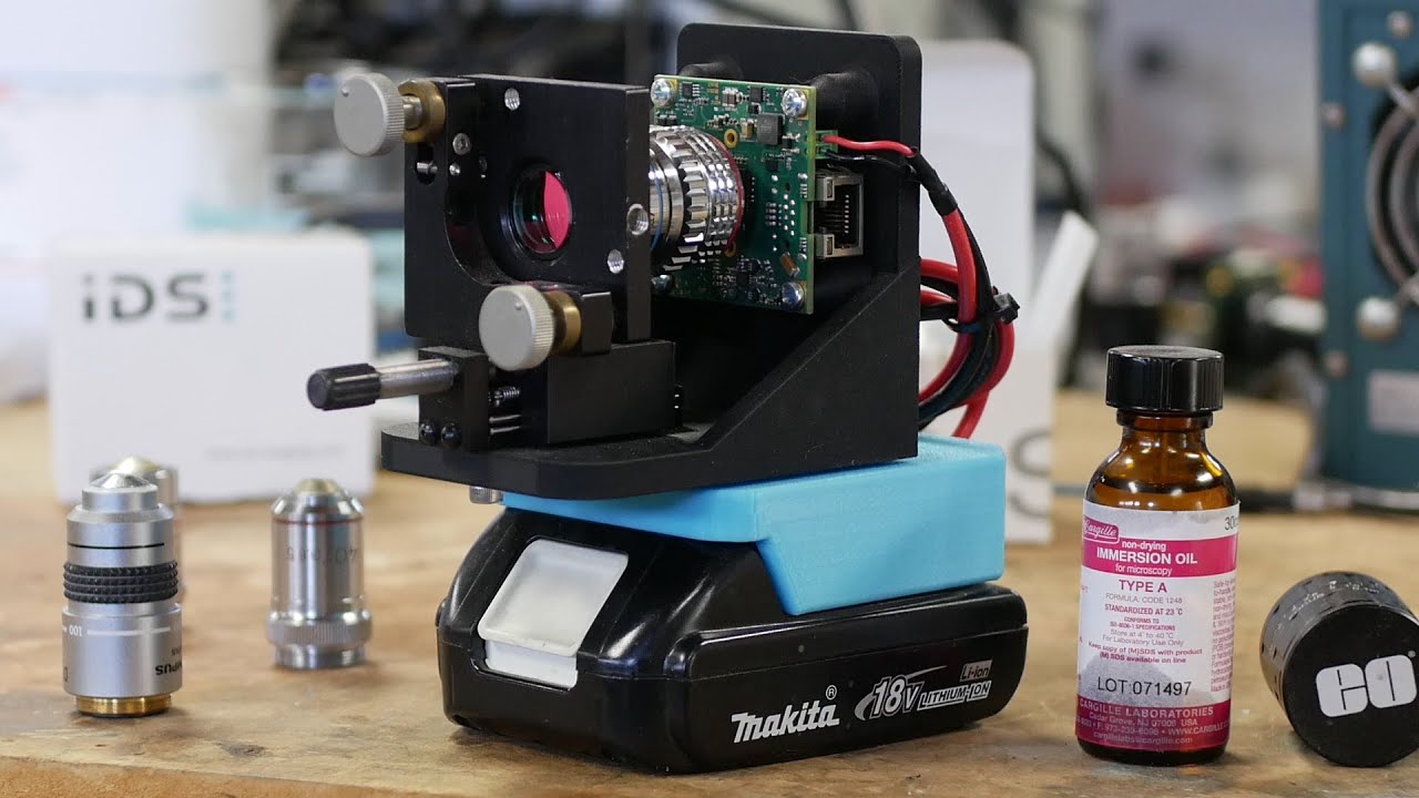
Today on Applied Science, I'd like to show you this technique of making defractive patterns on stainless steel with one of these Mopa laser engraver machines. These are a recently developed type of laser that give you very precise control over the pulse rate and the power in each pulse that the laser delivers. And the idea here is that we're going to pulse the laser and move it along at a rate that produces a periodic structure on the stainless steel. And that's what gives us this defractive pattern. If you haven't seen this before, it seems like, you know, alien technology. Um, these lasers are also good at colorizing stainless steel by growing an oxide layer on the surface. And you can control the oxide layer thickness so precisely that we can dial in an exact color. So, I knew you could do that when I got this machine from Cloud Ray. But the new thing is producing these defractive patterns through the same technique. we're going to grow an oxide layer and just make it periodic to produce this um defractive structure. So, in today's video, I'm going to show you how all this works, the settings you need to reproduce this, and even include some Python code on my GitHub that allow you to produce defractive images, images that have parallax, even almost holograms, but not quite yet. I've bought items from Cloud Ray twice in the past. once for my electrolless copper video from last summer and for a separate upcoming project. Um, and both times had great experience dealing with them, especially when ordering custom equipment uh that wasn't necessarily part of their standard options. So, that kind of led to us talking about doing this collaboration and Cloud Ray sent me this laser in exchange for making a video. I'm always happy to do that as long as I get enough time to come up with something that is genuinely interesting and novel. This is their GM 100 model, which is a 100 watt Mopa laser. And if you already have the 30 or 60 watt or want to save a little money, I'm pretty sure this same technique that I'm going to show you in this video would work on the 30 and 60 W models, um, since we aren't using the full amount of power. Of course, having the 100 watts is great if you want to cut through the metal when you're done making the pattern on there, if you're actually cutting out a complex shape. But just to make the defraction pattern, we're only using about 20% power of this 100 watt model. What's all this MOPA laser anyway? It's actually an acronym, master oscillator power amplifier, and it's describing an architecture of two parts. There's one part, the oscillator, which is a diode laser in many cases. I'm not sure if that's what's inside here, but I think so. And this is good because you can control diode lasers very accurately. You can pulse them on and off. the pulse length can be easily set and then you put this essentially low power pulse into an amplifier and the amplifier can be built so that it's only good at amplifying uh pulses linearly. So it doesn't really create its own pulse. It uses all of the temporal information from this diode laser. So this is great because then you get the timing accuracy of a diode laser and the massive amount of power you get from this fiber amplifier. This is in contrast to a Q switched laser where you're basically pumping that same fiber, but you need to have some way of opening and closing the fiber to get pulses out. Like if you want a pulseed laser because it's good for your process cutting metal or producing defractive patterns, you need some way of making the laser start and stop to make these pulses. And the way you do that is by putting a switch here. literally a way that uh converts the energy or allows the energy to exit this fiber since you're pumping it more or less constantly. The trouble is you have to wait for the gain medium, this fiber to charge up to a certain level and then when you open the switch, it all comes barreling out of here. So the repetition rate and the power in each pulse and the length of each pulse is determined mostly by how the laser is constructed and you can't really change it on the fly. Whereas with a Mopa laser, you can turn this on and off at any rate you want basically. And as long as you don't exceed the power limits of your amplifier, it just amplifies those pulses. Let's talk about the machine setup. Initially, I tried all kinds of different ways to hold the work down. As you can see, uh warpage is a really big problem with stainless steel. And so, one solution is to use thicker metal, which you should definitely do. But even with the thicker metal, you still need to have a way of holding this thing flat and um getting it to the focal plane repeatedly every time. One trick with this is we're doing something that requires a lot of precision and repeatability, getting this very accurate pattern on the metal. And that means that you have to achieve focus the same way every time. So if you develop a protocol, you really just have to make sure that everything is focused the same way every time you start out. And so one thing that helps a lot is to use this vacuum chuck. This thing has been a huge um benefit to this whole system. And this is not part of a this is not from Cloud Ray. I just found this on eBay. And the way I use it, you know, this hose is very flexible. You don't even have to clamp the vacuum chuck to the
Segment 2 (05:00 - 10:00)
table. I find it works best to just, you know, suck the metal down. That will hold it flat while you're engraving it, which is great. And it's also a heat spreader and a heat sink. So, if you are doing a thinner piece of metal, a lot of the heat will go into the aluminum here. And for precise precisioning, after the thing is pulled down, you can very easily move this thing around and get it right where you want it and then just leave it. This system also has a digital autofocus system. So, it has a depth gauge that measures the exact height to this laser spot here and a motor to raise and lower the arm. Um, I also like that they give you the option of just turning the crank yourself. So, since the height variation, I'm almost using the same thickness substrate over and over again, it's really nice to just set it up and then dial in the last half millimeter to make sure I'm at the exact right focal height. I used LightBurn to do everything that I'm going to show in this video and especially the material test feature where you can test two variables at a time to optimize your process settings. That was really critical. I went through, you know, dozens, probably not hundreds, dozens at least of these material tests to get this um defractive pattern working. And it's also nice that everything worked out of the box with the cloud ray system. You can see this laser also includes a camera over here. So, if you want to engrave something um on an object where the object has boundaries, it's kind of nice where you can calibrate this whole thing and then put the object where you want it. I tend to use the little framing feature in CL in the LightBurn a little bit more than this, but it is nice to have and the calibration worked without a hitch. Even though the stainless steel colorizing seems a little mysterious, let me show you how simple it can be. I'm just going to heat this piece of stainless steel up with a blowtorrch. And you can see there's colors of course. And uh if you look at the uh spectrum that we've got there, you can see it goes from straw yellow on the left through magenta, blue, green, and then kind of gray. Now, if we take a look at the test swatch here, thanks to Lightburn's material test, uh, as we put more heat into the material, we get the same set of colors where it starts off yellow and then orange, magenta, blue, and then it continues over here, blue to sort of green or sort of a teal color and then eventually gray. So the reason that we get these particular colors is because as the oxide layer gets thicker, meaning the temperature is higher and it grows a thicker oxide layer on the stainless, we get different destructive interference um with the wavelengths of light. And so you end up knocking out part of the spectrum and what's left is the color that you perceive. Even though if you search around on the internet, you'll find lots of different secret recipes of how to make colors on stainless steel, I really believe that it just comes down to the thickness of the oxide layer. So, I don't think there's any other way to make a color. I mean, if there is, please jump in with in the comments. But basically, once you've isolated this particular spectrum going from yellow through these colors, you've basically done it. I mean, it's there's no other way to get colors, I don't think. Um, if the color if you if none of these colors appeal to you, that's too bad. It's basically dependent on the fact that you're working with stainless steel and you're growing an oxide layer on it. That's actually where the colors come from. The nice thing is that in this particular material test, this is a six nancond pulse. And so, it's so fast that the surface of the stainless gets up to the right temperature before anything else has time to happen. like there's no chance that the heat is going to dissipate away. You basically bring it right up to the temperature you need and then you move on. But all of these other parameters affect it as well. I mean there is some amount of localized heating and so the stepover rate is you know sensitive but basically this whole thing depends on a lot of different process parameters. And so I'm going to this is all up on my GitHub. You can see exactly the parameters that I used but basically it just comes down to putting more heat in. And in this case, the main variable we're changing is the frequency. So going from about 200 kHz all the way up to about 7 or 800 kHz gets you that whole spectrum of colors. Just pick a different frequency, you get a different color. Keep everything else constant. To make things easy, I made a LightBurn file that's also up on my GitHub that has colors. The color recipes are set to the actual color layers in G in LightBurn. So if you import a SVG file, you can just point to the parts you want to be that color and assign them that layer and it all works out. So that's pretty nice. Um although I found to do things like this jackalantern for
Segment 3 (10:00 - 15:00)
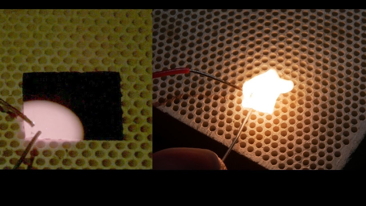
example, um setting up the SVG such that you can uh not have overlapping regions in the SVG is a big problem. Like most SVGs you'll download on the net or even ones that you draw yourself have overlapping regions. And this does not work well in LightBurn. actually have to have separate regions that don't overlap or you have to do offsets and it's just very timeconuming and so I thought wouldn't it be cool if there was some way to just import an image and um use a script or come up with some way of getting the image transferred so one of the things also on the GitHub is um a Python script that will take an image and look for the closest uh hue that is available in this limited pallet and then make an SVG that is uh filled up with these squares and Each one is just the separate layer. Like you basically it automatically figures out the right color. Now what's I only picked maybe eight or nine colors here total, but there's no reason you couldn't use all 20 layers in LightBurn and get 20 different hues. So originally I was thinking, wow, wouldn't it be cool? You could actually get full photographs in here. Yeah. The one problem is even though you might have, you know, quite 20 different hues, you don't also have simultaneous control over the saturation or the value. So, it's it looks good with cartoon characters that are saturated and don't have, you know, much else going on. I hadn't really try a photograph yet, but I think it's going to require quite a bit more tuning to make that work. As I was exploring my new powers here of colorizing stainless steel, I decided to make a birthday card for my mom. And I found there was one region that had this kind of sparkly character to it. Um I really stumbled into this by accident. In fact, originally I knew there was something called laserinduced periodic structuring. Lips is actually a thing in the academic literature, but it requires a polarized laser. So you'd have to take the thing apart and add a polarizer to the beam path, which I was prepared to do. But then I noticed you could actually get almost the same thing out of it with a completely stock laser just through this um very controlled pulse rate. So after I saw there was this hint of defraction, I spent quite a while dialing in the parameters and came up with some very good defraction gradings. They're actually very high performance. The magic speed and rate is 300 mm/s and 300 kHz. So the periodic structure has one micron pitch and that's a great size for um a diffraction grading. Originally I thought that the grading worked because of a height variation. It seems pretty reasonable that if you put this thing in a laser, it's going to basically make ridges. Like imagine like a stack of dimes uh from a welding setup. And so it's the physical height variation as this thing moves along that's causing the defraction. I don't think that's true. I think that the surface is almost completely flat and it's just the oxide layer thickness that matters. And interestingly, when you heat up a piece of stainless steel, the surface doesn't actually change height all that much. The oxide sort of grows down into the metal. And it's true that the surface raises up a very small amount, like maybe 10 or 20 nanometers. Now, the reason I say this is because I put a piece of this u defraction grading uh stainless steel into my electron microscope and had a really difficult time imaging the structure. It took a long time. I had to play with the acceleration voltage and the beam current, but eventually could see the structure. And I think this only worked because um at the just the right acceleration voltage and beam current, you know, the amount of secondary electrons coming out of this thicker oxide layer is slightly different. You can see the contrast. Um, I don't have any other uh tools here that I can use to really be sure, but I'm almost certain this is what's going on. So, really just having thicker oxide changes the um the phase delay. I mean, it adds like a little bit of phase offset, and that's how the def grading works. It's not actually physically there. This is important because originally what I was going to say you could do with this is make a silicone casting of the me of the metal after you've done putting an image or a nice sparkly pattern on it and then pull the silicone off and then use that as a chocolate mold. Right? This is something I've done in the past. And I thought, wow, wouldn't it be cool to actually have your own custom designs made with your laser and then put on the chocolate? I haven't tried this, but I suspect it's very unlikely to work because of this. The surface is actually smooth and the grading is built into the metal. It's not really sitting on top of the metal. After I had gradings working reliably, I started messing with the parameters again and was curious if I could get different pitch gradings to work, meaning the spacing would not have to be 1 micron. And it does. It works fine. 300 and 300 is a magic sweet spot, at least for this particular laser system. And the reason for that is that the heat input into the metal has to be just right to get just the right kind of oxide layer growing. So in other words, if you were to move at 100 millm/s and
Segment 4 (15:00 - 20:00)
did 100 kHz, the overall sort of heat affected zone would not be quite the same and it doesn't work as 300 and 300. So you have to stay fairly close to 300 and 300. But you can change the travel speed and adjust the pitch of the grading. Now, I also noticed that it's really easy to just put something into LightBurn, like a crazy shape, and have it trace it with the laser, and you can end up with a very complicated looking grading. Um, even though it's very simple to trace, the actual grading pattern is pretty complicated. Um, interestingly, the grading direction is perpendicular to the direction of the laser travel. So, you can see this with these uh circles that I made. If you create the circle concentrically, it does not look like a CD ROM because the defraction pattern is actually in the tangential direction. Whereas if you make the pattern radially, now it looks kind of like a CDROM because the pattern is now going um uh radially and you end up with you know the right kind of the look of a CDROM basically. But anyway, the point is that you can make very complicated structures. So you have full control over the angle of the grading and you have pitch control and that's pretty cool. Immediately I thought, "Oh, this is it. I have to make a hologram. " I mean, how could you not do it after you realize you have full pitch and angle control over a diffraction grading? So the first thing I attempted was to come up with this idea of breaking the image into pixels where each pixel is basically like an individual programmable defraction grading and you really do have control over the angle and the pitch of every single pixel in this image. So to start off, I just uh made a quick Python script that would take a black and white image and convert that into angles. And that actually has a pretty nice effect. It's very simple. It works every time. And it gives you a nice sparkly image that sort of changes character as the lighting and angles change around it. After playing around with this for a while, I figured out that you could simulate parallax by having um sort of a rolloff on the edge of an object. And so if you start off with an image and the dark parts of the image represent things that are far in the distance and light parts of the image are things that are very close to you, if you put it through this other Python script that's on my GitHub, it will convert that into sort of a gradient file where the edges of the objects go into a gradient and this translates into angles in the defraction grading. So, as the lighting direction is changed or if the image is tilted, it does look like some of the objects are moving left and others are moving right because that's how parallax works. Like the ones that are in front of the plane would be moving one way, the objects behind the other way. And I thought, boy, you know, it's just it seems like it's so close to being a hologram yet so close and yet so far. So, the trick is we are still limited by the size of the pixels. And in this case it's about a/4 micron or sorry a/4 millimeter size pixels square. And the reason for that limitation is um to fill in the pixel we have to fill it up with like three or four lines of defraction grading. And the start and stop point of the grading is not going to work very well. Obviously the stop point doesn't because it only leaves this diffraction grading as a trail behind it. So you're sort of burning up your usable pixel area by stopping and starting. And eventually if you get down to such a tiny pixel, there's really no grading left in there. So you kind of have to keep the grading at about 250 microns on an edge. And that limits how complicated your hologram could possibly be to the point where I'm not sure it's going to work. But I do really I hope someone out there is um excited by this and wants to help out because there could be some interesting stuff to do. Since I wasn't having much luck with the hologram approach, I came up with another interesting idea. Uh normally when you look at a diffraction grading, if the pitch is constant from top to bottom, imagine this column is the same pitch, it looks like a rainbow because the angle changes when you look at the top of the column versus the bottom of the column. If you trace the rays from the light source to the defraction grading to your eye, it's going to be different at the top than the bottom. But what if we linearly varied the pitch of the grading such that you saw you perceived the same color from top to bottom because we've just smoothly adjusted the grading. And then I thought, well, yeah, that's great. Now we have pitch control. We could um put an image in there and expect to get something that's true color. So, for example, if you wanted at one particular angle, you could see a color image where blue is really blue, green is really green, red is really red at that one exact angle. And we can do this because we can compensate up and down the hologram or diffraction grading so that the pitch is always right to send the right color into your eye. So I have scripts to do this as well and it works kind of okay. Um I got these, you know, parrots here in this gecko and the colors were a little fanciful anyway, but it's with tuning and a little care, it's actually getting kind of close. It's just the
Segment 5 (20:00 - 22:00)
viewing angles are so picky that h it's kind of a niche use case, but still pretty cool. By the way, all of this code that I wrote actually came from Gemini. I haven't really tried a lot of different AI coding solutions because, you know, Gemini was one of the first ones I used and it just works really well. In a lot of cases, it worked on the first try because these scripts are so simple and so easy to describe. So, I've been completely thrilled with the ability to write code that would take me hours or days in just minutes. Um, it's perfectly suited for this kind of thing where the input and outputs are so well specified. Another limitation is that all of these um very dense defraction pixel images really push LightBurn and the whole pipeline pretty far. So some of these SVG files can be as big as like 80 megabytes and LightBurn will load it and you can move it around in LightBurn pretty easily. But then when it comes time to cut it, there is some optimization step that you can't quite get around. I know LightBurn has this optimized cut path choice. And I always turn that off because if you turn it on, it's never able to optimize 80 megabytes worth of cuts. It just spins forever. But if even if you turn the optimization off, um it's not uncommon for LightBurn to need like 10 minutes. It looks like the program has crashed. It's actually still running. I've never actually had it crash and refuse to come back, but you have to walk away and get a sandwich. And when you come back, it's, you know, it's 10 or 15 minutes later and then it's ready to cut. Once the thing starts cutting, I have not had any problems at all. It's really just this pre-optimization step, which I don't think needs to happen. But anyway, it's a very um weird file to cut and I can see why no one who's working on LightBurn had ever thought to test something quite like this. But just FYI, start off with a really small image if you're testing any of this stuff out and then work your way up. So anyway, I hope you found that interesting and uh like I say, if someone wants to help me out with the hologram stuff or make any contributions to the GitHub, please by all means, I think this is going to be a really cool thing. All right, see you next time. Bye.