Today on Applied Science, I'd like to show you the process of making permanent magnets from just iron and nitrogen. That's right. The excitement here is that the iron nitride crystallin structure has the potential to be even better than neodymium. And it has the benefit that you're making it from iron and nitrogen, which are two of the cheapest materials around. You don't have to find a source of the neodymium. The challenge is that no one's been able to actually pull this off just yet. So, in today's video, I'd like to show you a process that was outlined in a paper. Uh, we're going to make some iron nitride powder in a planetary ball mill and then test it in a vibrating sample magnetometer. The process to make iron nitride powder is surprisingly simple. We just take ammonium nitrate and iron powder and mix them together very vigorously. so vigorously that the ammonium nitrate decomposes and the resulting nitrogen atoms diffuse into the iron. Um, basically pounding it so hard that the nitrogen just goes into the iron particles and then we cook it at about 200C for a long time which allows the iron nitride phase to grow. As you can imagine, the nitrogen doesn't really want to diffuse through the solid iron. So this process that we're going to develop has to also grind the iron particles to really small size. Even if we start with a fine powder, we're going to have to get down to the nanometer scale just because the nitrogen doesn't penetrate very far into the iron even with this vigorous mixing process. So you might think, well, if we need grinding of particles and this energetic mixing, a ball mill might be a perfect solution for this. In fact, maybe you've seen the demo where you take two hardened bearing balls and smash a piece of paper between them. And if you look at it, you can see the paper is actually burned. It smells burned and it even looks kind of burned around the impact. So, this is a great way to do this high energy uh mixing at the same time grinding the particle size down. Another name for ball mill is rock tumbler. You've probably seen these before. You just load up everything you want to grind inside here. And when we turn it on, it just rotates around and everything in there gets ground up on top of each other. Now, if we wanted to grind more aggressively, either more quickly or get more energy released at those impacts. We could spin this more quickly, but eventually if we spun this fast enough, everything inside there would just fling out to the in to the outside of the barrel and the grinding would stop entirely. So, the thing that limits the power that we can get into our mixture with this type of grinder is not the power of the motor, but the strength of gravity. Um, there's just no other way to make the physics happen in there without a stronger gravitational field. So, we could go to a planet with stronger gravity and carry this up there. Or we could build a planetary ball mill. A planetary ballmill allows us to grind at arbitrarily high values of energy because we can simulate sort of any gravity we want. Imagine that this ballmill was on the end of a long arm and we were spinning it around kind of simulated gravity style on a sci-fi space station. Here we can just spin this thing faster and get any gravity force we want. Another nice feature is that the rotation speed is locked to the revolving speed through this belt system so that we're always getting the optimal amount of spin for a given, you know, simulated gravity. Um, you can imagine if there was like a separate electric motor here, we could eventually turn up the rotation, the revolving speed so high that we need more rotation to get the optimal amount of grinding. So, this one has a ratio of -2:1. You can see that the chambers counterrotate again to get the maximum amount of churning and stirring in there. Um, now clearly I'm not the first person to think up planetary ball mill. You can go on eBay and find planetary ball mills, but the problem is that even the used ones and the cheap import ones and even the used cheap import ones are thousands of dollars. But an even bigger problem is that they're huge and heavy. You can imagine that even with careful balancing, this thing is going to produce a lot of vibration and noise. It's actually kind of terrifying. And so the professional units have an enclosure and they're they weigh hundreds of pounds to sort of, you know, handle all of the vibration that's going to come out of this. So I thought, well, you know, I can clamp it to my bench and save on all the weight and ballast. And, you know, it's this whole applied science YouTube channel is basically an excuse to just build stuff in the shop. So, I mean, why wouldn't I? And, uh, I made the plans for this all open source and it's on GitHub. And so you can um get all the CAD and all the sourcing for the parts and everything. I believe the parts cost was about $1,000 including the motor, which is a clear path servo motor. I measured the total electrical power going into the motor when the thing is completely empty and versus when it's loaded with the grinding balls and the powder in there. And the difference is 1 to 200 watts. So in other words, all of that energy is going into the mechanical grinding almost 100
Segment 2 (05:00 - 10:00)
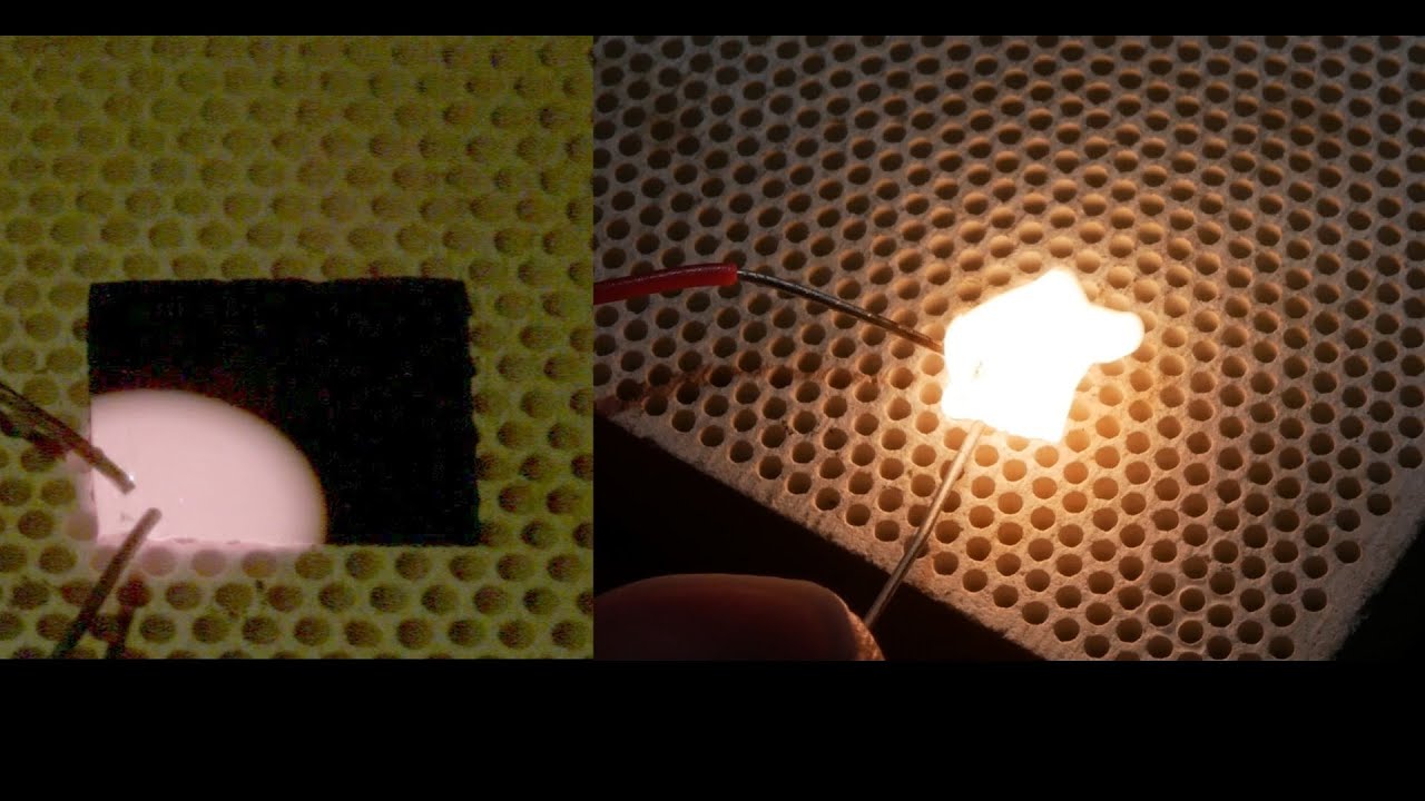
watts per chamber, which is a substantial amount of energy. It's enough where thankfully this thing without an enclosure actually cools itself down because it's moving through the room temperature air and kind of, you know, cooling itself down that way. But if you're if your sample is temperature sensitive, be aware that it's going to get quite hot. I mean, 100 watts concentrated in here is going to raise the temperature quite a bit. Uh, it's also if you just need to grind something, not just make magnets or whatever. It's an amazingly powerful grinder. I put a couple pieces of microscope slide in there and with a clear lid, used the high-speed camera to see what was going on. And in just five or 10 rotations, it had already turned a couple pieces of microscope slide into a powder. It's just an insanely powerful grinder. And so in this project where I was using this to make the iron nitride powder, after 3 days of constant grinding, the particle size is getting down to 1 to 300 nanometers. It's a good grinder. Another feature of this grinder is that the chambers are hermetically sealed. So you can use a little laser cut flat rubber gasket on here and then the steel lid just pinches it down onto this stainless steel pipe fitting. And the edge is a very high quality lip there. So it makes a good seal. And this is important because the authors of the paper that I was following said that the process is air sensitive. You need to grind it in a sealed chamber. And even when it's time to open the chamber, you got to do it in a glove box in an inert atmosphere. And I thought, yeah, well, you know, that's nice for peer-reviewed. But really, this is just a demonstration YouTube video, so I can withstand a little bit of oxidation. So, imagine my surprise when I opened one of these chambers after a few days of grinding and was surprised to see that a few particles ignited as they fell down through the air. It's pyrohoric. And so, I don't know how, but I somehow didn't learn my lesson from that and spooned out a little bit and put it into a plastic bag, which then proceeded to melt into my hand. So, yeah, it's reactive stuff. And to be honest, I think I probably did lose some of the potency there. Um it's also possible that what was burning was just um raw iron was just oxidizing very quickly because it's at nanocale. Anyway, so luckily I have two chambers and so in opening the second one I was a little bit more careful and made a glass ampule and flooded it with argon and then very gingerly still had to open the chamber in air because one I don't have a glove box and two it's even if I did it's not going to be big enough to get this whole ball mill into. But anyway, spooned some into the glass ampule with argon and sealed it up and then got it into the kiln for this um annealing step. Um the paper sort of glossed over this. They just said, you know, it's about a day at 200C, but if you go above 200C, you can ruin the um the crystal structure that we're looking for. There's actually a specific iron nitride phase that we're trying to grow, not just any old iron nitride. It's got to be alpha doublep prime uh iron nitride. And so by choosing this temperature to be 180 or 190° C, you're basically preferring that specific crystallin structure. Kind of like tempering chocolate. After spending a day in the kiln, uh it's time to convert this powder into a solid shape so that we can test it. Uh the challenge is we can't center it together like we can with lots of magnets because the structure is delicate enough where if we went above 200 C, we lose the structure. So centering is out. And in the paper they were advocating this approach called shock compaction where basically just set off an explosion and blast the powder into a solid. Um that's nice but I don't have that kind of a setup going. And so instead I decided to just cast it into epoxy because I could very easily do that. And my idea was that even though I don't have a glove box and an inert atmosphere to do this, if I get the powder into epoxy quickly enough, it will kind of, you know, keep the oxidation to a minimum hopefully. And so I did that and managed to get about a 50% bymass epoxy blob going. And to make the little magnets, one for the vibrating sample magnetometer, I just put it on the end of the probe that you'll see. And then to cast some magnets to test sort of the bigger magnets, I made um TPU printed molds and sprayed them with a little mold release and then put the epoxy into those molds. I also cast one in a magnetic field to see if there was any sort of effect of um orienting the grains of this thing as it was curing, as the epoxy was solidifying and then also just cured a bunch outside. And lo and behold, it does work. Uh it is a magnet. Um but it's very weak magnet. It doesn't even hold itself up against an iron surface. Um but it is possible that I ruined it by having too much oxidation in there. I don't have the equipment right at working at the moment to analyze the nitrogen content of this thing. I also made some castings of the raw iron powder to see if just the iron alone would function as a permanent magnet. And as you can see, there's a very slight effect, but it's not nearly as much as the iron oxide or potentially
Segment 3 (10:00 - 15:00)
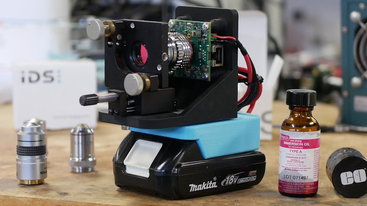
iron nitride that we made. A vibrating sample magnetometer sounds like a very complicated piece of equipment, but I guarantee you've seen one before, and maybe you have even held one in your hands. That's right. An electric guitar pickup is exactly the same thing. Uh, we've got a permanent magnet in here, a vibrating sample, which doesn't have to be a magnet itself. It just has to have magnetic properties like these steel strings and then a coil to pick up the voltage induced by this moving um thing that has magnetic properties in a static magnetic field. Okay, let's talk about how this thing is built. The vibration is created by this loudspeaker at the top here. And I 3D printed some parts that connect the loudspeaker cone to this hollow carbon fiber shaft. And the whole idea of this wooden frame and everything is just to get the loudspeaker far away from our measurement area. Of course, we've got a magnetic field in the loudspeaker that is exactly in phase with what we're trying to measure. So, we can't have that be very close at all. The next thing we need to do is measure the position of this rod very accurately. We can't just sample the electrical signal going into the loudspeaker because there's going to be phase delays and distortion and all kinds of things. we really need to know where this sample is in space with a very high degree of certainty. Now, the professionals use a linear variable uh transformer, but I didn't have time for that. And so, what I did is I just mounted a linear potentiometer into the speaker itself. And this is great because I can put a voltage on that potentiometer and then the voltage that comes out of the third terminal of the pot is exactly the position of the sample. So, it's easy to incorporate into the signal chain. Okay. Hey, then we have the electromagnet that takes the place of the permanent magnet in a guitar pickup. We're basically going to slowly cycle through different static magnetic fields to check how they affect the properties of the material that we're vibrating in there. And this is the same electromagnet setup that I've used in previous videos. It's got about 50 mm diameter pole pieces and it's made from mild steel. Soft iron would be better. Soft meaning the iron conducts magnetic field very well, but it doesn't retain it very well. and mild steel is almost as good in that regard. Um, the copper coils are the same ones that I've used all along, but I painstakingly rewound them onto these 3D printed polycarbonate forms. And the reason I did that is because I knew I was going to need water cooling, and I needed to get them onto a bobbin that would fit onto my pole piece, and this was kind of the only way to do it. Um, the whole process went fairly well. I'm kind of surprised that the 3D printed polycarbonate bobbins are basically watertight. If the pressure isn't too high, they really don't drip at all. If the pressure is too high, uh the water does permeate through the 3D printed material. There's no leak at a gap as far as I know. It really just permeates through the material, which is, you know, just kind of a fact of 3D printed parts. The magnet is designed to run at about 60 volts at 20 amps. So 1,200 watts peak. That's why we need the water cooling, of course. And you might be thinking, well, if I want the most efficient magnet, like how do I get the most field? This magnet will produce about 1. 6 Tesla in that gap of maybe 5 to 8 mm. And you might be thinking, how do I design a coil to get the most magnetic field out of it? Well, you know, it's interesting. If you're definitely going to use copper, then it doesn't matter how many turns or how many amps you've got. As long as you're maxing out your power supply in terms of power, then the only thing that matters is the mass of copper that you're using. You might think, well, if I used fewer turns and more current, that could be different, right? Like that would be a different situation. But it's interesting. It kind of, like you say, as long as the mass of copper is the same, then that means the cross-sectional area of your coil is the same. and you could have as many or as few turns in there as long as it's well matched to your power supply. So unless you're going to wind the coil out of silver, there's actually nothing you can do other than add more and more copper, which will get you a bigger magnet. Of course, the next thing we have is a magnetic probe, which is this uh thing at the bottom here. And this is just a commercial off-the-shelf magnetometer that measures the strength of the magnetic field in the electromagnet. And then the last thing we have here are the pickup coils themselves. So just like a guitar, this is basically a humucker design. I know the first time I heard that phrase was like a humucker. It sounds like a humding dinger, but no, the reason that guitar players call it that is because it bucks the hum. If you just have a coil of wire out in a room somewhere, you're going to pick up all of the hum from the mains wiring that's in the walls of your building. So by putting the coils next to each other like that, we can make it very sensitive to changing magnetic fields that are between the two coils, but relatively insensitive to changing magnetic fields that are outside of those two coils. So the next question is, how many turns should your pickup coil have to get the most signal? I got a kick out of this cuz when I was researching how to build a vibrating sample magnetometer, lots of
Segment 4 (15:00 - 20:00)
people say, "Oh, you should have more turns to get more signal. " And it's true. If you ask guitar folks as well, they'll say, "Oh, yeah, more turns is a hotter signal for sure. " But that's only partially true. More turns means more voltage, but again, the universe doesn't really know or care how many turns you have. The only thing that matters is the cross-sectional area of your coil. And so if you only have one turn, that means yes, the voltage will be much lower, but the current has to be higher because with the same amount of conductive stuff in your coil, it doesn't matter if it's 10 turns or a million turns. If this moving magnetic field induces something in your coil, you can't just sort of get rid of or create more power. Really, the dynamics here are the changing magnetic field and again, how much stuff is in your coil. It doesn't matter how it's divided. The only reason that people say more turns means more signal is because everyone is thinking in terms of voltage. However, if your amplifier is set up to have a low input impedance, in other words, it's going to draw a lot of current out of those coils, then you could very well get by with fewer turns. And in fact, there is such a thing as a single turn guitar pickup uh made by a company called Alumatone. So, I've never seen or used one of these in person, but it's pretty impressive that literally one turn of aluminum is enough to get a great sounding signal out of a guitar. Um, funny enough though, they have to use a little transformer built into their pickup to convert that super low impedance single turn, high current output into a much uh higher voltage, lower current signal because it has to be compatible with all the existing guitar amplifiers out in the world. In this case, there's another practical consideration. We really just don't have that much physical space in there to put our pickup coils. And so, if we went in with a coil that looked like this, you can see how thick it is. There's just no way to get lots of turns in there um because they just take up a lot of space. And so in this case, we're maybe willing to give up some total amount of signal in order to get those pole pieces closer together so that we get a better control, a more uniform and a higher static magnetic field from the electromagnet. So I found a good solution to this. Uh DigiKey sells really flat coils intended for charging cell phones and things like that, NFC and wireless charging. And so they're already stuck together very flat and I just glued them into a little 3D printed piece and soldered them together and got a really nice um four coil setup that I just stuck onto the um pole pieces. So then we take the output of those pickup coils and go into a lockin amplifier. And conveniently this amplifier has both voltage inputs and current inputs. And the impedance match for the voltage inputs is like a 100 megga ohms. And the current and the impedance match for the current input is essentially a dead short. So it can handle signals from both a single turn coil or a you know a coil with a very large number of turns. If you're not familiar with a lockin amplifier, what this does is it amplifies signals only that are in phase with a reference signal. Um, it's really good for laboratory measurement techniques where you know something is going to happen at a specific time and you only want to amplify signals that are changing in just the same way. So if our input signal is coming from the pickup coils, where do we get the reference? Well, that's just the potentiometer showing us the position of this sample. So all we have to do is feed that plane voltage signal coming from the potentiometer that measures the position of this sample, this vibrating sample. feed that into the reference and then feed the input signal from those coils. Now, this is super sensitive. If you're measuring things like magnets, permanent magnets, or even making your own, you know, potentially crappy magnets out of iron nitride, you don't actually need a lockin amplifier. This thing will amplify things down into the nano volt range. And even really, really bad magnets like the one we made today, um, will produce much, much more signal. In fact, I almost had too much signal and had to attenuate it. This is the commercial off-the-shelf uh magnetometer that I'm using just to measure the magnetic field in the gap there. And I think professionals don't do it this way. They actually characterize their electromagnet and then just measure the current going into the electromagnet instead of measuring what's actually going on in the gap there. That's not how I did it. Um but anyway, this is just a lowass filter that takes the signal from the magnetometer and feeds it into the oscilloscope. The oscilloscope can then monitor the output from the lockin amplifier, the amount of current going through the um coils, the frequency that the thing's being vibrated at and everything. And uh we'll zoom in here and show you all the graphs that I've got on the screen. Okay, so I've got all the power supplies turned on and we're looking at the oscilloscope here. And so the yellow trace here is the reference signal that's going into the lockin amplifier. This describes the exact position of our sample in the magnetometer. So the amplitude of this signal is very important. We don't want it to change much over time because that
Segment 5 (20:00 - 24:00)
would mean that um the signal that we get out of the magnetometer might be drifting over time. So I've set up a little histogram here that shows the most recent 5 or 10 seconds of this signal. So as long as the histogram is not moving and looks, you know, relatively normal in distribution, we're good. If this is drifting around or if it has a bad distribution, we'll know that the signal is probably not that reliable. The next trace down, the blue one, is the amount of current being commanded to go through the electromagnet. The green trace is the magnetic field sensed by that magnetometer that's in the gap. And the orange trace is the signal from the lockin amplifier. And then on the left we've got an XY plot showing the signal from the lockin amplifier, the pickup coils basically plotted against the magnetic field in the gap. And this is essentially the BH curve that everyone talks about. I've got a video that I made a while back describing the BH curve a little bit in more detail. This basically shows how difficult our easy our sample is to magnetize. So if we were to put a piece of iron in here, it would very easily become magnetized and then saturate at some value versus if we put a piece a permanent magnet in here like a neodymium magnet. As it turns out, a 1. 6 Tesla field, which is about the maximum that this system can go, is not enough to demagnetize a neodymium magnet. Nor is it samarium cobalt magnet. Interestingly, I'm going to press the trigger button on the signal generator, which is going to start sweeping the current up slowly at first and then more quickly as it gets going. And what we'll see is this thing is going to trace out a curve. Now, I've set up the time base of the oscilloscope so that the persistence in this XY plot will end up showing us the whole graph. And I've timed it out so that the time that it takes for the current sweep to happen will fill up the screen just about right. So, I'll do some time lapse here. Okay, so we've completed a cycle and as we can see there is actually some area inside this curve. Generally materials that are magnetically soft, meaning they conduct magnetic fields well, but they don't retain fields well, will have no area inside the curve. They always pass through zero every time. Now, the sample that's in there now is some of our iron nitride magnet. So, it's not a very good magnet. In fact, compared to ceramic or samarium cobalt or alnico or basically any other kind of magnet, it's not very good. But the fact is that there is area inside the curve here. So it has some retentivity and some coercivity giving it some area inside the curve. This whole setup is very useful because if you're going to improve this process, if we're going to adjust the ball milling parameters, the you know the heat treatment parameters and all that stuff, we need a way to really accurately characterize the sample in the same way every time. very accurately, which is what this machine does. Another interesting thing I picked up, if you want to compare your results to some other researcher in a different part of the world, how do you describe how sensitive your machine is? There's so many parameters like the, you know, the size of the coils in the pickup, you know, the speed of the vibrations, the distance of the vibrations, all these things actually get compensated out by a single calibration parameter. What we do is we load up 100 mg of pure nickel and put that into the vibrating sample magnetometer and all of the geometry system parameters can be canceled out by measuring the saturation value for pure nickel where if we crank up our magnet as high as it goes, eventually we don't get any more signal out because the nickel has completely saturated and you're just not going to get any more signal out. And so for 100 milligrams of nickel, there's this conversion. EMU is the unit that all these folks use. And then you can just calibrate your entire machine out and compare uh samples to different locations in different research groups. So anyway, I think I might actually have to do a follow-up here. It does seem like maybe trying this again with a better control over the atmosphere and the handling of the powder and preventing oxidation and doing some measurement to see if there actually is nitrogen in the solid phase are all good things to test and we can, you know, check on that to see if we're actually improving the magnetic properties using this setup. I hope you found that interesting and I'll see you next time. Bye.