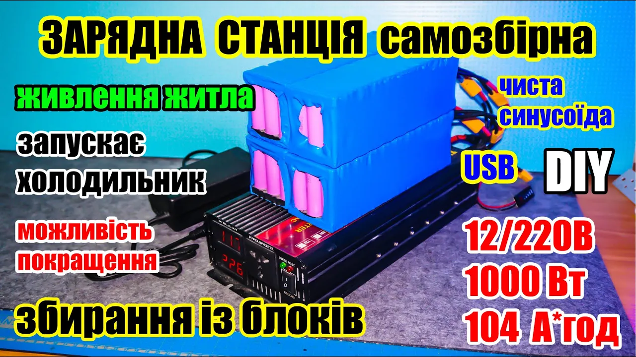
🔋⚡Simple homemade CHARGING STATION "for $100", 400W (1000W) + 400Wh battery. From blocks.
Machine-readable: Markdown · JSON API · Site index
Описание видео
⏩ Greetings! In this video I tried to show how you can assemble a simple and inexpensive charging station with a capacity of 400W and a battery of 36A*h (400W*h) with a pure sine wave at the output, from which a REFRIGERATOR, boiler, pump and other electrical equipment can work, you can also power a home from such a charging station. (Pure sine wave inverter). Such a station cost me about "$100".
🍺 Special thanks to those who support the channel with donations and thanks to the channel sponsors.
💲For monetary gratitude💲
👉 https://send.monobank.ua/jar/6dKFDUky7i
⏩ Links:
⚡👉 https://fas.st/KeOxe - popular budget inverters TATALIKEN
⚡👉 https://fas.st/W9dZIn - high-quality inverters HOULI
⚡👉 https://fas.st/2vyZmQ - high-quality inverters HOULI (more powerful)
✅ https://fas.st/GDu7XQ - charger 12.6V 20A
✅ https://fas.st/rQfOq - charger 12.6V 10A
⏩ Spare parts:
✅ https://fas.st/v5jyA - White BMS 3S 100A with balancer
✅ https://fas.st/zQ3T3o - capacitor active balancer 3S
✅ https://fas.st/lhSRu1 - plastic holders for Li-ion 18650
✅ https://fas.st/Jnu7B - 18650 insulating rings
✅ https://fas.st/2cuymT - 0.15x8mm nickel-plated tape
✅ https://fas.st/CbFh_ - USB phone charging module
✅ https://fas.st/Bko58 - 4-port USB phone charging module
✅ https://fas.st/SqOjMv - battery charge level indicator (Li-ion 3S)
✅ https://fas.st/422PV - XT90 power connectors
✅ https://fas.st/7xZFUa - silicone wires (12AWG, 16AWG)
✅ https://fas.st/GwvFUo - heat shrink for battery assemblies
✅ https://fas.st/tfDJu - tips, select according to the diameter of the inverter terminals (I bought them at an electrical goods store)
⏩ Measuring devices:
✅ https://fas.st/a-wYGp - Smart Multimeter GVDA GD128
✅ https://fas.st/hkKKO - Current clamps GVDA GD166B
✅ https://fas.st/0Icuw9 - Oscilloscope DSO152 FNIRSI
🎬👉 Instagram - / radiolabpro
📲👉 Telegram channel - https://t.me/RadioLabPRO
#18650 #inverter #refrigerator #Ukraine #chargingstation
👍 Thank you for your time!
⏰ Timing:
00:00 - Introduction
00:43 - assembling a 3S12P Li-ion 18650 battery
06:44 - measurements and checking the assembled battery
08:24 - CC-CV charger
08:37 - 1000W inverter (2200W)
09:04 - assembling an adapter with a charge level indicator
10:00 - assembling a charging station
11:04 - assembled charging station
11:37 - connecting various loads to the charging station
17:50 - charging the assembled charging station
18:57 - operating time under a 100W load
20:00 - safety rules
20:23 - cost
20:44 - conclusions and recommendations