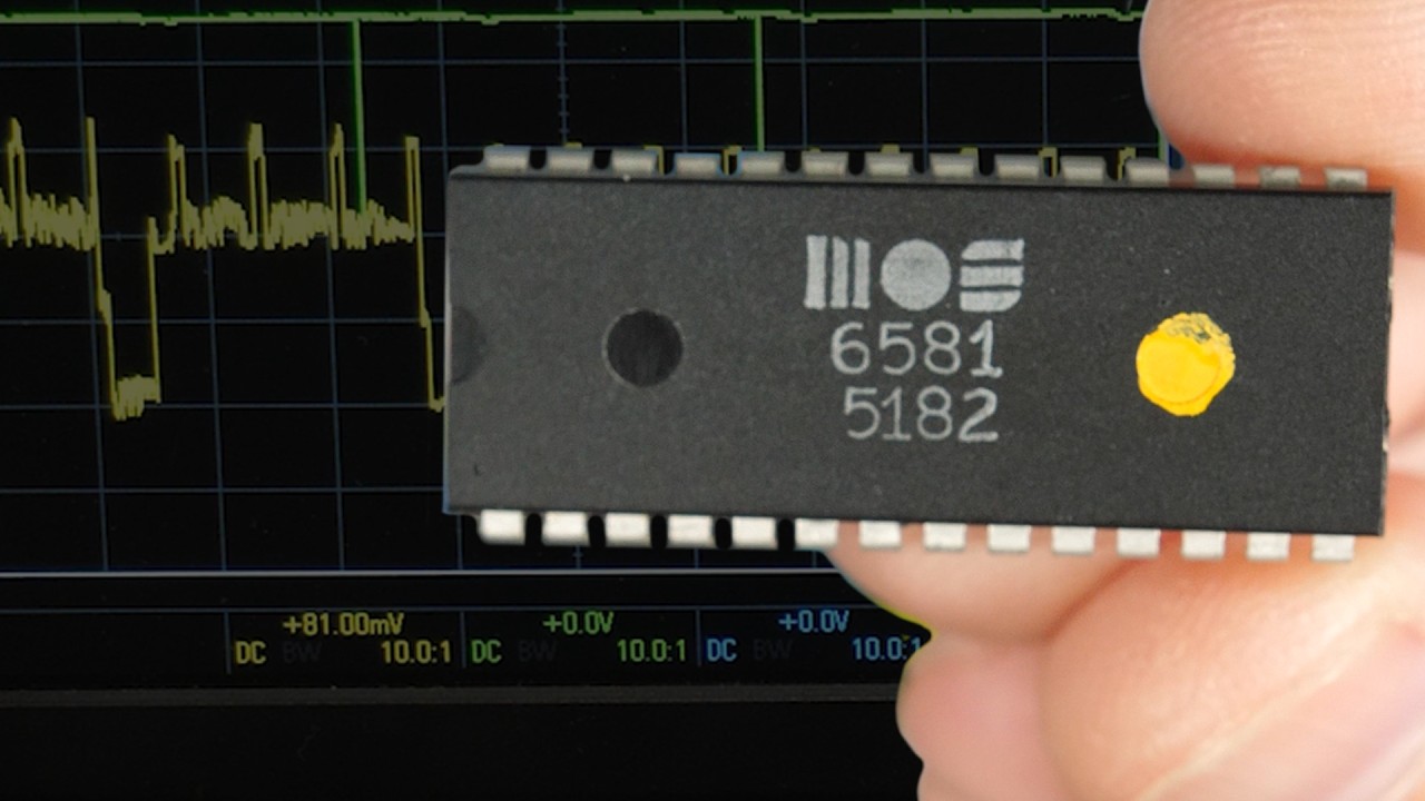
In my last video, I explored the sound interface device or SID chip from the Commodore 64 computers. I hooked it up to my breadboard computer here and went through many of the different things it could do and even got it to play some music. The only problem with this chip though is that it's no longer being produced. And because of how uniquely capable it was for its time, there was a lot of creative stuff done with it, like this song. And thus to this day, the chip is very much sought after. So what do you do if you want to experiment with it on your own? Well, it turns out there's a couple different modern clones that work as basically drop in replacements, or maybe a better term rather than clone as emulators because they use modern microprocessors. So in this video I want to look at a couple different replacements, see what it takes to get them working, and maybe compare how they sound to the original. And the idea here is that if you wanted to play with this yourself, it's a lot easier to get a hold of these modern replacements than it is to find a genuine original SID chip. But either way, if you want to play with it on your very own 6502 based breadboard computer. Just a reminder that I sell these kits on my website, iter. net 6502 that include the basic components for the 6502 and a few extras that you might want. I don't currently sell any of the SID replacement options or of course the original SID chips, but if you get any of them, I've got pretty much everything else you need, so check out iter. net 6502 for more information. The first replacement I came across is the sidkick Pico and it's open source, and so this is the GitHub repo for it. And the readme here sort of explains everything, but I definitely found a few things confusing including, you know, just how to get the thing and what to get. I guess the preferred way to get a hold of these is to order your own PCBs from PCBway here, optionally with the parts already soldered to the board. There's also a few other sources for assembled PCBs that are maybe a little more straightforward, but either way there are a few different hardware versions to choose from and you want to make sure you get this right. It's a little unclear to me why you'd want some of these, but for example, the first one here is the Skpico with pwm or external dac. And I'm not entirely sure what this is about. It doesn't have a DAC or digital analog converter, meaning it doesn't have an analog sound output, which seems weird for a sound chip to not output sound. And I'm just guessing that's because if you're trying to create a higher than original quality replica of the classic 8 bit Sid sound, you know, maybe you would want this and then, you know, to be able to provide your own DAC that's maybe higher quality, but that's probably not what we want. You know, we want something that's more like a drop in replacement. So I got this SKPCO with onboard DAC and here's that board. We've got version 0. 2 with the DAC. That's very important. And so you say, okay, how is this a replacement for this chip? And well, we've got to add a couple rows of headers. So we add a row of header pins here and then we'll have to solder these on. But then this becomes a replacement for this and it just plugs in the same as the chip does. You'll notice though, there's a couple missing pins here. So what's up with that? So these first four pins are missing. If we look at the datasheet for the sid, those first four pins here are for connecting two capacitors. And I guess the SID kick doesn't need those external capacitors because it has everything it needs on the board already. Well, almost everything it needs. It also needs a Raspberry PI Pico microcontroller to run the software that it uses to emulate the sid. So we've got another two rows of headers over on this side that we use to connect the Raspberry PI to. So, so we'll add these two rows of headers and then the Raspberry PI goes on like this, I believe, and that all sandwiches together like that. Obviously this is not 1980s technology anymore, but we'll solder this all together and then it's got a few more pins here. So it's got these four pins here, which we'll talk about here, in a minute, as well as another two here that are used for some other options that this has. So once it's all soldered together, we need to make sure we're running the right software on the Raspberry PI. It says the SK Pico PCBs don't need to be programmed in any way. The Raspberry PI Pico does need to be flashed with the pre built binaries which are available in the release package. And the procedure is pretty simple. You just press and hold the button on the Raspberry PI, connect it to the PC and then it'll just show up as a USB drive and we have to copy the firmware, the UF2 file to that drive and. And then it'll just automatically reboot. We just want to make sure we do that before we plug it into the actual 6502 computer. Now it talks about the release package. So if we go up here, there is a release package over here. Releases. So this is the latest release and you can download this zip file here. So if we download that and unzip it, there's a whole bunch of stuff in here. And we've got hardware version 2 or point 2. And even in here there's a whole bunch of different options, but we've got the version with the DAC, so version point 2 with the DAC. I think we could also use this one. And it'll blink the LED on the
Segment 2 (05:00 - 10:00)
Raspberry PI when it's making sound. So that could be useful for troubleshooting. So we'll go with that one. So here's the thing, it's all soldered together. And to do this, we hold down the button and plug in the USB and yeah, this is USB micro. And then let go of the button and that shows up as this Raspberry PI RP2 here. And so if we take that file that we found, this DAC LED and copy that to the Raspberry PI, it'll go ahead and copy that. And then the Raspberry PI reboots on its own and disconnects. And so then we can go ahead and disconnect it from the USB and we should be good to go. Now, one thing I found that's a little bit clunky with this is that, you know, the SID chip is obviously a lot smaller. It's got the same pin out there. But getting this to fit in the breadboard was a little bit of a challenge. So I came up with these extensions that I can kind of put on here. That gives me a little bit more room to get it into the breadboard around everything else. So that's the completed thing. And this has enough room to fit in there. So in theory this should maybe work. Now I've got the original SID chip out of there. Everything else is still hooked up just the way it was with the original SID chip. So let's try installing this contraption here. And that should be it. We'll go ahead and reset the computer. And so with that in there, we can start trying to play some music. But before we do that, after my last video, many people pointed out that the music I was playing was designed to be played on the Commodore 64 in Europe, or at least outside of North America, which used a 50 Hz PAL display interrupt for timing, not the 60 Hz interrupt that I assumed in my last video. So to play this at the proper speed, let's take the 1 MHz clock that I've got in there and divide that by 50 Hz and that's the that. And we convert that to hex, we get 4e20. So if I set address CA to 4e24e20, that should set the interrupt timer to 50Hz. And so with that done, let's try playing the music. So we'll go address 4. 00 and run. So I see the interrupt happening here in green, and you can see it's 50 hertz or thereabouts. So we fixed that, but I don't hear anything. And that's because by default, the SID kick doesn't actually output sound on the output pin. Weird but true. And I think the idea is that if you're using this to replace a SID in your, let's say, vintage Commodore 64 or whatever, maybe it's because you want better sound quality and also because this emulates two SIDs so you can actually get six voices instead of three. So in that sense, this is a bit of an upgrade from the original chip. And so then, rather than routing the audio back through the motherboard where it might lose quality, the actual output is right here on these pins here. So if we connect our output, or our the recorder that you're listening to this output pin. There you go. And it's actually working pretty well. And I can hook the scope up there as well. And here are the docs where it talks about this. So it says, for best quality, connect the DAC output on the SKPICO to the audio video socket or to any other audio jack or socket. So that's what we're doing now. And it says to output the sound via the SID socket, you need to close solder jumpers. It says the one marked with L outputs the left channel through pin27, which is the standard audio output. And it says, note that this way audio goes through the circuitry on the board and quality suffers a bit. So I guess that's why it doesn't do it by default, but we can try that. So here's the solder jumper marked with the link. So I'll add some solder to close this. That way, in theory, this will now work as more of a drop in replacement for the original SID chip. And the problem here is that the solder mat, there's solder mask between the two pads for the jumper. And you know, the thing with solder mask is that it resists solder. So maybe if I can glob enough solder here, this really isn't working and now I'm knocking resistors off the board. So let me try and fix that. And yep, that solder mask is still working as solder mask. You know, it might help if I get rid of some of this flux. You know, usually flux is a good thing because it helps the solder go where it's supposed to go. But in this case there's solder mask there and I wanted to go where it's not supposed to go across the solder mask. So let me try with a big glob of solder that doesn't have any flux in it. And hey, there we go. Yep, that looks like I've bridged that solder jumper. Well, that was more work than it needed to be, but I think I got it done without any collateral damage. Well, let's put this back in the circuit and I'll reset the computer. So I moved the scope probe and the connection to the recorder that you're hearing back to the SID output. And since I never powered the computer down, everything should still be in ram. So let me just run address four zero and for some reason it's really
Segment 3 (10:00 - 12:00)
distorted and I'm honestly not sure what's going on here. You know, there's apparently a bunch of configuration you can do via a program that runs on the Commodore, but I can't easily run that program since I don't have a Commodore. So I don't know if there's maybe some sort of gain adjustment or something that could be tweaked, I don't know. But either way it definitely works if you're happy using the separate output pin here, which you know, seems reasonable enough for a project like this. You know, it's not that critical that it comes out any particular place. You know, if you're just looking to make sound. This, this does it. So that's the SID kick. But as I was looking into replacements for the sid, I also came across this, the ARM sid. It claims to be A plug and play replacement of the 6581 and it is a real plug and play solution. Just insert instead of the original SID chip into the socket and it's done. Accurate sounds, significantly lower noise level, less interference, sounds amazing. And here it is. In fact, the form factor is pretty similar to the original SID chip. So this is kind of nice. Looks like it'll fit a lot neater into the breadboard. So I've got everything set up here again as if the original SID chip was there. And so let's see if this ARM SID is in fact truly plug and play. So I'll stick it in the computer where the normal SID chip would go. I'll reset, then address 400 and run. And it works. Well, that was pretty easy. And the other thing to note, you know, with both of these replacements is if you remember, the original SID chip required this extra 12 volt power input. It didn't just run off the 5 volts supply for the regular computer. Both of these replacements, we can remove that 12 volt power input to get rid of that. This is that 12 volts I was injecting. We can get rid of that entirely. The whole thing runs on just the 5 volts, so that's pretty handy, you know, and all of these sound pretty good to me. But what I can do is edit together a mix of the original, the SID Kit Pico and the ARM SID and let me know if you hear a difference. But you know, to me it seems like either of these options makes a good substitute for the original. If you can't find it, one thing you'll notice is that the output levels are a bit different. The ARM SID is quite a bit lower than the others. To make it easier for you to compare. I'll try to adjust all the levels to be about the same when I edit this together. So hopefully you found that interesting.